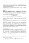
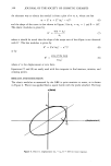
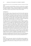
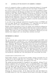
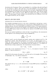
MECHANICAL PROPERTIES OF SKIN 337 sional translation stage firmly mounted to a Ralmike's portable toolmaker's bench (South Plainfield, N.J., Catalogue #085-3). This arrangement allows for maximum mechanical stability, required for accurate stress-strain measurements, and simulta- neously provides a portable yet secure work surface for mounting the electronics (Figure 1). A Tektronix FG-501A function generator, slightly modified to enable accurate adjustment of the D.C. offset using an auxillary 10-turn potentiometer, was used to drive the force coil of the GBE head at a sinusoidal frequency of 2 Hz. The other electronic components are analogous with the description by Christensen and Hargens (17,18). One major improvement is the use of a digitizing oscilloscope (Tektronix 5223 with 5B25N time base generator) for capturing force and displacement traces. These traces are transferred to a Tektronix 4051 computer equipped with a signal processor (4051R07) to enhance data analysis. Every eighth point of each trace was recorded on magnetic cartridge tape for later analysis. For instrumental measurements, panelists would lie on their side on a portable cot, and were requested to remain as still as possible. Attempts to restrain movement of the leg with straps were abandoned when it became apparent that this method applied Figure 1. In vivo GBE Apparatus. a) Ralmike's portable toolmaker's bench #085-3. b) Nitrogen tank (regulated to 5 psi). c) Tektronix 4051 computer. d) Shaevitz CAS-025 signal conditioner for LVDT. e) Tektronix 5223 digitizing oscilloscope. f) Tektronix FG-501A function generator with modified offset potentiometer. g) Control for translation parallel to GBE axis. Cable drives one axis of Ralmike's 023- 700R positioning table. h) Ralmike's #060-2-2 right-angle lead screw slide. i) GBE head mounted in a swivel lock attached to the lead screw.

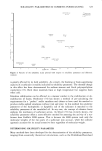
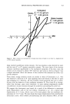
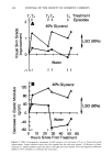
338 JOURNAL OF THE SOCIETY OF COSMETIC CHEMISTS unknown tension to skin in the measurement area and actually increased panelist move- ment due to discomfort. Contact between the dynamometer and the skin was achieved with double-sided tape (3M, No. 666©). A circular disk of tape of diameter 4 mm was placed on the skin and a bushing insulator (Amphenol 31-1099), a plastic disk with a hole drilled through the center, was placed on top of the tape. A wire probe (from the armature) was bent 90 ø to form a hook which fits into the bushing insulator. The possible influence of tape occlusion at the test site was ignored since the viscoelastic response appeared to be independent of time. The elasticity values for the first experiment represent averages of three traces from one site of the lower left leg. In the glycerol treatment study, the GBE measurements represent averages of two traces obtained from three sites on each leg, approximately 10, 15, and 20 cm below the knee joint, centered on an axis through the knee and ankle joints. Four fiducial marks on the calf outlining the rectangular treatment area were used with a template to place the GBE probe to within 1 cm of each of the three measurement spots (see Figure 2). No template was used to position the probe in the first study. The force coil driving amplitude was adjusted at each measurement site to provide a maximum armature displacement of only _ 0.75 mm from equilibrium in an effort to minimize the contribution of nonlinear viscoelastic response, as will be discussed later. The oscilloscope was operated in left-versus-right mode, displaying stress-strain ellipses which varied slightly with time due to panelist movement and respiration. The operator would examine a series of traces with time and save only the traces which formed closed loops with symmetric shapes. Data Analysis. An oscillating stress (force) is applied to the skin and the resulting strain (displacement) follows with a certain lag or phase shift (8). For a linear response, one writes the stress as: and the strain as o' = o' o sin (cot ß = ßo sin (cot) If the stress is written as cr = o' o cos 8 sin cot + o'o sin 8 cos cot, the elastic or shear storage modulus is defined as (21) (1) (2) (3) (T O E' = -- cos 8 ß0 and the viscous or shear loss modulus is defined as (4) (T O E" - sin 8 (5) ß0 Thus, from a plot of ß and o' vs. time, one can determine O'o, ßo, and 8. This type of analysis can be done with use of the time base generator to obtain stress and strain as a function of time.
Purchased for the exclusive use of nofirst nolast (unknown)
From: SCC Media Library & Resource Center (library.scconline.org)