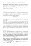
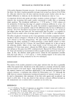
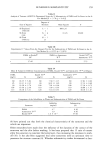
MECHANICAL PROPERTIES OF SKIN 339 Figure 2. Placement of GBE probe for measurement on lower leg sites. a) Positioning of 4-mm double- sided adhesive tape circle by means of a template. b) GBE attached at the central site. Three of the four fiducial marks which outline the treatment site and which are used to position the template are visible.

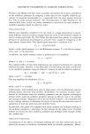
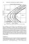
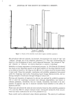
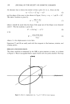
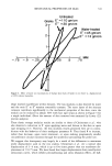
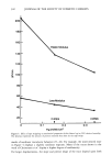
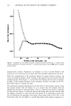
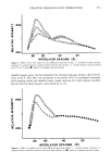
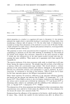
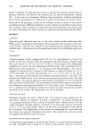
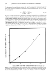
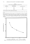
340 JOURNAL OF THE SOCIETY OF COSMETIC CHEMISTS An alternate way to obtain the moduli is from a plot of (y vs. ½, where one has • = E'½ + E" (½02 - ½2) 1/2 (6) and the shape of the curve is that shown in Figure 3 fore o = •o = 1 and8 = 60 ø . The elastic modulus is given by •(e = eo) E' = (7) •0 where it should be noted that the slope of the major axis of the ellipse is not identical with E'. The loss modulus is given by E" = E'e'/(eo 2 - e'2) •/' (8) or by area of the loop E" = (9) 2 qT •0 where ½' is the displacement at zero force. Equations (7) and (8) are easily used with the computer to find maxima, minima, and crossing points. RESULTS AND DISCUSSION The elastic modulus as measured by the GBE is quite sensitive to water, as is shown in Figure 4. Water was applied from a squirt bottle with the probe attached. The loop o (force) Oo •o (displacement) Figure 3. Force vs. displacement (g0 = ½o, • = 60ø) for linear response.
Purchased for the exclusive use of nofirst nolast (unknown)
From: SCC Media Library & Resource Center (library.scconline.org)