32 JOURNAL OF THE SOCIETY OF COSMETIC CHEMISTS skin is passed over the sensing element and changes in the conductivity of the surface of the element (which reflects changes in the sweat output of the skin area enclosed by the collection chamber) are monitored and displayed by electronic recording instruments. A variety of transducing systems have been employed in sensing elements and some of those mentioned in the literature are listed below: 1. Changes in resistance of a sodium chloride crystal (55), which proved unsatisfactory because of lack of standardization (52). 2. A hygroscopic plant pith whose resistance changed with vapour pressure (56). :3. Dissociation of lithium sulphate (5:3). 4. A thin film of hygroscopic lithium chloride (56). 5. A layer of phosphorus pentoxide between two platinum wires (5:3). 6. Changes in resistance of a coating of carbon on a polystyrene plate (5:3, 57). In practice, several elements may be used for detecting changes in sweating rates. For example Bullard (56) generally used one wide-range element covering the RH range of 5-40%, and up to six narrow-range elements each covering a different RH range, in steps of 9-12ø/0, and could switch from one element to another. Changes in resistance of the elements were displayed on a strip-chart recorder. With these methods the rate of air flow is of paramount importance the flow rate and relative humidity must be adequate to ensure complete and rapid evaporation of moisture without causing local cooling of the skin which might inhibit sweating. In order that the air passing through the collection chamber did not become saturated Bullard (56) used a sufficiently high flow-rate to ensure that the effluent RH did not exceed :30%. When using humidity sensing elements calibration of the elements is essential. From the calibration curves the relative humidity values of the air emerging from the collection chamber can be determined. Using these values the amount of water evaporated from the skin can be calculated from the relative humidity change (ZXRH) in the gas as it passed over the skin surface, from the air flow, and from the temperature: Sweating rate = Air flow X ARH X Density of saturated steam (mg min- l) (1 min- 1 ) 100 (mg 1- •) (The density of saturated steam at the temperature of the experiment can be obtained from Handbook Tables). A correction for surface area may be applied if required.

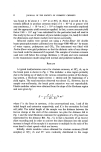
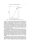
MEASUREMENT AND CONTROL OF PERSPIRATION 33 Instead of having a constant air flow and monitoring changes in rela- tive humidity, a predetermined constant RH can be maintained in the collection chamber by varying the air flow (58). The humidity sensing element forms part of a Wheatstone bridge sweat present in the air current alters the resistance of the element and unbalances the bridge. The signal resulting from this imbalance is used to regulate dry air flow and so restore the RH in the collection chamber to its original level. This technique is claimed to be extremely sensitive and capable of detecting an increase in sweating of the order of 0.08 mg within the chamber and the authors claim that the system can be used in the axilhe. Galvanic skin resistance The galvanic skin resistance has been used to measure the sweat gland activity in rats (19), and Bettley and Grice (53) used it to indicate the presence of sweating within a collection chamber attached to the skin. However, although the galvanic skin resistance largely depends on sweat secretion, it also varies with changes in vascularization of the skin, and is not a specific indicator of sweat secretion (9). Absorption of infra-red radiation An entirely different approach to the quantification of sweating rates has arisen from the fact that water vapour absorbs infra-red radiation (59). In the method published by Johnson and Shuster (60) infra-red radiation from two sources passed through two conductor tubes, and then into two chambers of a detector. One gas stream was dry, but the other gas stream came from a collection chamber attached to the skin and so consequently contained water. In this detection chamber radiation was absorbed by the moisture and gave rise to an imbalance between the two sides of the de- tector the imbalance was measured electrically, amplified and displayed on the calibrated meter of the analyser, which in turn was connected to a recorder. There is a linear relationship between the area under the cali- bration curve and the volume of water analysed, this area being dependent on the flow rate of dry gas. Direct recording of axillary ratio James (28) recorded the axillary ratio itself, rather than its components, by using an x-y recorder. Perspiration from each axilla was collected by gas
Purchased for the exclusive use of nofirst nolast (unknown)
From: SCC Media Library & Resource Center (library.scconline.org)