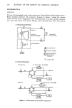
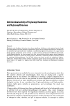
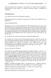
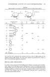
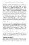
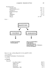
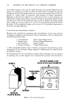
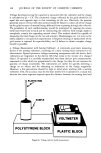
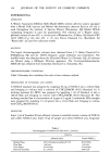
314 JOURNAL OF THE SOCIETY OF COSMETIC CHEMISTS more kinetic energy in the event of a spark discharge. In an aerosol filling room, the energy of a charge on an aerosol can which has been tossed or propelled by puncture through the air should be greatest when the can reaches the greatest distance from the ground or a large surface of grounded metal (position of lowest capacitance). Discharge in this location might be to a small piece of wire or metal projection. It follows that a charge energy which is known to be safe at this position should be safe anywhere else. It may be concluded, then, that in order to estimate the highest energy that a charge on a can may attain by E = Q2/2C, the two following parameters should be known: 1) The coulombic charge on the can and 2) The minimum capacitance at which the can might discharge. B. ELECTRIFICATION MEASUREMENT METHODS Recently, four methods for measuring static electrification of cans have received investigative emphasis in aerosol products industry laboratories. These are listed below and will be discussed briefly. 1. Coulombmeter: 2. Faraday Cage: 3. Grid Collector: 4. Sensing Voltmeter: Direct Charge Measurement Induced Charge Measurement Charge Transfer Voltage Measurement I. Direct Charge Measurement. Figure 3 shows an arrangement for performing a direct measurement of the coulombic charge, adapted to measurements on aerosol cans by the DuPont Company. In this illustration the can is mounted on a plastic block although it can be mounted on anything, even a metal support, that is insulated from ground. The leads from a SAMPLE GROUND BEVELED PLASTIC BLOCK KEITHLEY MODEL 61OC SOLID STATE ELECTROMETER PUNCTURING DEVICE Figure 3. Direct charge measurement.

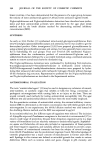
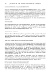
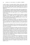
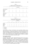
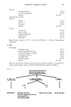
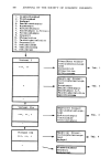
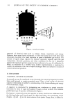
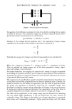
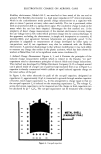
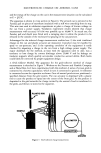
ELECTROSTATIC CHARGE ON AEROSOL CANS 315 Keithley electrometer, Model 610 C, are attached to bare metal of the can and to ground. The Keithley electrometer is a high input impedance (10 TM ohms) instrument, which in the coulombmeter mode permits charge measurement on a capacitor with plus or minus 5 percent accuracy when used carefully. The can is punctured, either with an air-powered drill or a spring-driven spear. The coulombic charge is read on the meter when the can has been emptied. Advantages for this method are: 1) the simplicity of direct charge measurement 2) the internal electrometer circuitry keeps the can voltage low (a few volts) which prevents charge loss by corona-discharge 3) the apparatus, excluding the electrometer, is simple and inexpensive to construct 4) reproducibility and agreement between laboratories are potentially good 5) the procedure is adaptable to measurement of charge developed by either spray or can-puncture and 6) can capacitance may also be estimated with the Keithley electrometer. A potential disadvantage is that without modification it may lack ability to measure any charge that resides in the plastic activator, which has been shown by workers at Metal Box, Ltd. to be significant under some conditions (5). 2. Induced Charge &leasurement. Figures 4, 5, and 6 illustrate the principles of the induced charge measurement method which is related to the Faraday "ice pail" experiment used to demonstrate principles of electric fields and charge inducement. This method was developed by Phillips Petroleum Company (3). If a charged aerosol can is placed inside of a larger can or pail 'but kept insulated from it as in Figure 4, a capacitor is thereby constructed which exhibits an equal induced opposite charge on the inner surface of the pail. In Figure 5, the other electrode (or pail) of the can-pail capacitor, designated as capacitance C,, approximately 10 pf, is connected to ground through another capacitor of known, much larger capacitance Cm. In this arrangement a charge equal to that on the can-pail capacitor Cx is induced on the measuring capacitance C,•. The voltage 1/,• across the known capacitance can be measured and the charge on both capacitors can be calculated by Q = C,•I/,•. The can-pail capacitance can be measured with a bridge 4- - + + - + + - + + - + + - + + - + +++++ + METAL SHELL {FARADAY PAIL} I Figure 4. Can-pail capacitor.
Purchased for the exclusive use of nofirst nolast (unknown)
From: SCC Media Library & Resource Center (library.scconline.org)