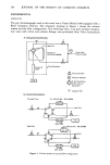
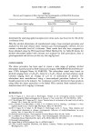
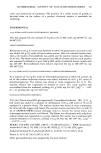
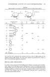
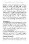
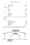
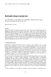
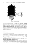
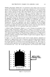
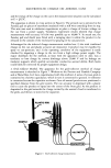
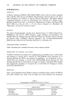
JOURNAL OF THE SOCIETY OF COSMETIC CHEMISTS v t Vx + • • '. ß ß c x•10pF i -. _.• C m • 60,0pF rn V=O ........ Figure 5. Faraday cage method analysis. Cm is the known capacitance (large compared to Cx) Cx is .the capacitance of the aerosol can (measurable) and Vm is the voltage measured across C• (small compared to Vx). Q = c•,v•, = CxVx. Ex = i111111111 elm (1) AEROSOL CAN (2) FARADAY PAIL (3) METAL SHIELD (4) FOAM INSULATION (5! CAPACITOR WITH CAPACITANCE Cm (6) CAN CAPACITANCE Cx (7) ELECTROMETER & DIGITAL MULTIMETER (6) BATTERY (9) CAN CHARGING WAND Figure 6. Faraday cage apparatus for aerosol can electrical measurement.

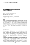
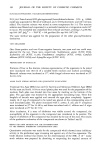
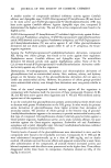
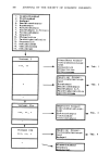
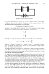
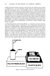
ELECTROSTATIC CHARGE ON AEROSOL CANS 317 and the energy of the charge on the can in the measurement situation can be calculated as E = Q2/2C. The apparatus is shown in cross section in Figure 6. The aerosol can is pictured in the Faraday pail on pieces of styrofoam insulation with a stiff wire extending from its top. This wire was used in validation experiments to place a charge of known voltage on the can from a power supply. Validation experiment results showed that charge measurement with accuracy of 0.5% was possible up to 10,000 V. In actual use, the Faraday pail and shield were fitted with a swinging door to allow the product to be released to the outside of the enclosure by spraying or by can puncture. Advantages for the induced charge measurement method are: 1) the total combined charge on the can and plastic actuator are measured 2) product may be expelled by spray or can-puncture and 3) the operating condition of the equipment is easily checked by imparting a charge to the can from a high voltage power supply. The major drawback for the method, at least with the apparatus used to date, was a tendency to lose charge by corona discharge above 25,000 V and by leakage on insulator supports which quickly accumulate conductive aerosol debris. Both faults could likely be corrected by proper equipment design. 3. Grid-Collector &lethod. The apparatus for the grid-collector method of charge measurement is sketched in Figure 7. Workers at the Proctor and Gamble Company and at Metal Box, Ltd. have experimented with this method. A series of screen grids is connected to a known capacitance, which in turn is connected to ground. A voltmeter is connected across the capacitor as shown. Cans of aerosol products are positioned a specified distance from the grid system. The can actuator is depressed with a plastic rod to cause the product to spray into the center of the front grid. As the product is deposited in the grid network the charge carried by the aerosol cloud is transferred to the grids, and thence, is stored in the capacitor. •,•TIC ROD SCREENS SAMPLE VOLTMETER CAPACITOR Figure 7. Grid-collector charge measurement. GROUND
Purchased for the exclusive use of nofirst nolast (unknown)
From: SCC Media Library & Resource Center (library.scconline.org)