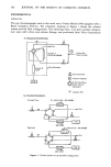
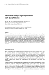
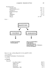
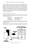
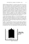
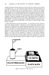
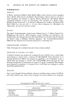
318 JOURNAL OF THE SOCIETY OF COSMETIC CHEMISTS Voltage developed across the capacitor is measured with the voltmeter and the charge is calculated as Q = CV. The coulombic charge collected by the grids should be of equal size and opposite sign to that remaining on the can. Obviously, the greatest potential source of error with this method would be failure to collect all of the charge on the grids because of material being deflected from or passing through the collector. The possibility of such malfunctioning would be minimized by tapering the screen mesh sizes from front to back and by constructing the collector with enough depth to completely contain the expanding aerosol cloud. This method should be capable of measuring the total charge on the can and actuator. Disadvantages are: 1) it may not be easily adapted to can-puncture experiments 2) frequent cleaning or replacement of the grid system is required for reproducibility and 3) failure to obtain complete charge transfer is possible. 4. Voltage Measurements with Sensing Voltmeters. A commonly-used static measuring device is the sensing voltmeter, consisting of a static sensing head connected to an electrometer. Figure 8 pictures a voltage-measuring arrangement with the device. Such voltmeters are responsive to the electric field that exists in the vicinity of a charged object. If operated in a carefully standardized way these devices give measurements, expressed in volts, which are proportional to the charge, but they do not measure the quantity of charge (coulombs). The instruments are useful for quickly detecting a charge on an object and for obtaining an indication of the charge magnitude. However, a few precautions should be kept in mind when working with a sensing voltmeter. First, the accuracy may be less than desired if it is operated in a casual way because the meter response depends upon the distance between the sensing head and P/IC ROD SAMPLE POLYSTYRENE BLOCK PLASTIC BLOCK Figure 8. Voltage (electric field) measurement.

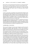
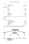
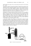
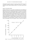
ELECTROSTATIC CHARGE ON AEROSOL CANS 319 the can as well as the geometry of the can. Therefore, the meter should be recalibrated in the environment and with the particular type of can for which it is intended to be used. Second, significant charge loss may occur by corona discharge as a result of the very high voltages on highly charged cans. Thus the can surroundings to several inches should be cleared of metal projections even then some corona losses may occur at the very high voltages of 100,000 v or more that may develop. Third, the sensing voltmeter alone is not capable of providing enough data to calculate the charge and its energy for this, the can capacitance must also be determined under the same conditions that the voltage was measured. C. ESTIMATION OF MINIMUM CAN CAPACITANCE As already emphasized, the minimum capacitance that a can may transiently possess in an aerosol filling room situation is an important parameter to measure. This minimum capacitance might be expected to approach the self-capacitance i.e., the capacitance in free space. The self capacitance of a 4.25-in-diameter sphere, with about the same surface area as a 16-oz can, estimated by C = 4 7r e eo r, is 6.0 pf (picofarads) (4). In Phillips Petroleum Company laboratories the capacitances of suspended cans of various sizes were estimated using the arrangement shown in Figure 9. The can was hung by a non-conducting polypropylene cord six feet from the floor in a I2 x 12 x I2-foot laboratory room containing a few randomly placed metal objects. The can was charged with an accurately measured voltage (2000 to 20,000 V) by 4 1/2' 6 1/2' ROOM SIZE 12'x 12'x 12' Figure 9. Can capacitance measuement: 1) High voltage power suply 2) High impedance volt meter 3) Kiethley electrometer 4) Digital multimeter.
Purchased for the exclusive use of nofirst nolast (unknown)
From: SCC Media Library & Resource Center (library.scconline.org)