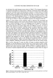
92 JOURNAL OF COSMETIC SCIENCE confocal microscopy uses a reflected signal to form an image whose contrast is improved by strong reflection and by a limited lack of photons due to absorption and scattering. Moreover, confocal microscopy of the skin requires real-time imaging to limit blurring caused by motion, i.e., blood flow pulses and involuntary movement. Until recently, the tandem scanning microscope (TSM) was the only technique having this prerequisite of real-time imaging, since confocal laser scanners (CLSM) would typically need a few seconds to form an image. In 1991, the first in viva images at the surface and below the surface of the skin were obtained by using a TSM-based ophthalmoscope (6). From this first attempt, a commercial TSM was redesigned in 1993 (7) for in viva skin imaging with the development of a skin-contact stabilization device fitted around an objective lens that flattened the skin and limited image shifts. The Anderson team (8) solved the slow scan drawback of the CLSM in 1995 by introducing a rotating polygon mirror in the scanning path that produced video-rate images of the human skin in viva. We describe in this report the design of a new video-rate CLSM prototype adapted to the in viva exploration of human skin that produces sharper reflected-light images. It has been used to depict the various epidermal layers. An explanation of the strong reflection of the basal keratinocytes is proposed. The influence of sun exposure on cellular damage and on melanin migration was likewise investigated. MATERIALS AND METHODS THE IN VIVO CLSM PROTOTYPE The prototype was constructed around the compact Oz fast-scanning confocal module manufactured by Noran Instruments Inc. and with the contact-stabilization device designed in-house. A Nikon x40, 1.30 N.A., oil-immersion objective lens of 160-mm tube length was screwed into a microscope tube directly attached to the scanning-light exit of the confocal module. The rapid Z direction scan (up to 30 optical sections per second) was performed by moving the objective lens with a piezoelectric driver having a maximum travel of 350 pm. The contact device was centered in front of the objective lens. The distance between the lens and the contact tip can be adjusted with coarse and fine manual screws (Figure 1). In this configuration, it is the objective lens that moves vertically while the skin surface remains fixed. The confocal scanner has a two-channel configuration that permits simultaneous imag- ing of reflected (scattered) light and fluorescence contrast. A galvanometer-mounted mirror was used to scan the slow axis while an acousto-optic deflector (AOD) was used to scan the fast axis. The latter was a solid-state device that provided variable scanning rates ranging from several seconds per image up to 30 images per second and higher. It was designed to deliver 1000 resolved points within its operating range. The confocal head was suspended from a cantilever arm that gave access to the skin surface of the whole human body (9). Easy positioning of the scanning head was provided by a motorized stage. The light source consisted of a Krypton/Argon laser with power limited to 2 mW at the objective lens in order to avoid photodamage to the skin tissue. The laser provided three wavelengths: 488,568, and 647 nm. A Silicon Graphics workstation was used to control the system and also performed the capture of a digital image stream generated by the control electronics. The acquisition time was limited only by the

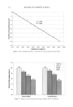
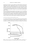
IN VIVO CONFOCAL MICROSCOPY 93 scalmer piezo driver• objective lens • contact device•T• contact device skin Figure 1. Schema of the in vivo confocal module. Rapid Z-scan piezo objective driver and contact device. availability of memory space (RAM) in the workstation, but was typically about ten seconds for standard size images (512 x 480 pixels) at video-image rates. The control electronics regulated the position of the piezo driver through the piezo control by synchronizing the driver with the timing of the video stream. Thus, the acquisition of depth series (Z-series) or time series (t-series) was done at intervals fast enough to avoid severe shifts between the optical sections. The resulting image stack (data sections) could then be processed in a few minutes for volume rendering and thickness measurements of the various epidermal layers (10). Z-series formed of 80 optical sections separated by 1-pm steps were acquired on the forearm. The stacks were processed with the OTIP3D software (LISA Labs, CPE, Lyon, France), using first the wavelets algorithm (11) for noise reduction and then the region- growing algorithm (12) for the binarization of convex features. The 3D reconstruction could easily be examined from any view angle with the volume-rotating capability of the software. SUN EXPOSURE EXPERIMENT Two volunteers spent one week on a Caribbean beach, free of any experimental con- straints. Subject A was a 32-year-old male, having skin phototype III according to the classification of Fitzpatrick (13). Subject B was a 30-year-old female, having skin pho- totype IIi. In vivo confocal images of the dorsal forearm of each subject were recorded using the blue laser line before exposure (TO), two days after the ten-day trip (T12), ten days (T20) and 30 days (T40). The stratum corneum thickness was automatically mea- sured by using the OTIP3D software from six stacks of optical sections per time-set. RESULTS REFLECTION IMAGES OF THE EPIDERMIS Keratinocytes of the spinous layers of the epidermis were identified by their dark nuclei
Purchased for the exclusive use of nofirst nolast (unknown)
From: SCC Media Library & Resource Center (library.scconline.org)