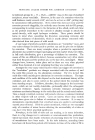
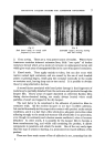
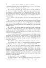
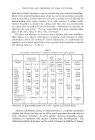
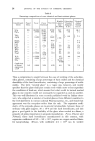
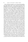
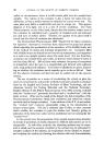
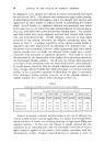
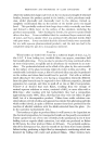
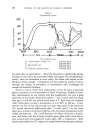
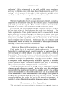
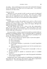
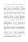
PROTECTIVE LACQUER SYSTEMS FOR ALUMINIUM CONTAINERS chemical resistance of one of these types is sufficiently high in relation to the product with which it is envisaged to be used, and its other properties satisfy the conditions required for container work, the lacquer itself becomes the least important factor governing the success or failure of a protective system. It is rare when examining a lacquer failure to find that the lacquer itself is at fault, and it is equally rare to find a lacquer that has failed because it has been chemically attacked. Such failures can nearly always be attributed to factors associated with the metal container itself, the lacquer application, or quite often, incorrect determination of the basic characteris- tics required in a protective film in relation to a particular product. The first point to be realised is that all protective lacquer films are permeable and transmit oxygen and water. Nevertheless, they do provide protection, if applied in the correct film thickness, for a particular product. For every lacquer, in relation to a specific product, there exists a minimum film thick- ness which must be exceeded before any significant protection is afforded. If this threshold figure is not exceeded, then no matter how continuous the film, corrosion of the underlying metal will take place. There is also a limit with single lacquer systems, of the maximum film thickness, as particularly with Epoxy resin systems, adhesion falls off rapidly when the film becomes thick. LACQUER DAMAGE The next point to be considered is the influence of minute pinholes. One or two imperfections in the film can be highly dangerous if the surrounding film is such that it is appreciably conductive. It can then become cathodic to the few pinholes and the very dangerous combination of a small anode and large cathode then exists, which intensifies corrosion to a point where rapid penetration of the metal at the anodes takes place. On the other Fig. 1. ½) (6) Lacquered aluminJure showing two types of underfilm corrosion.

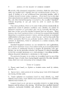
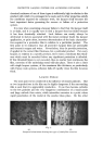
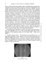
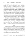
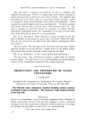
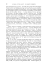
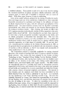
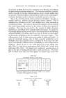
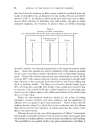
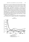
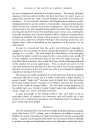
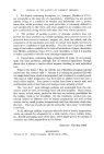
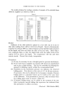
6 JOURNAL OF THE SOCIETY OF COSMETIC CHEMISTS hand, a thicker film having a larger number of pinholes may perform satis- factorily, for under this condition corrosion at the sites of imperfections may rapidly choke itself, whilst the thick film does not become cathodic. Because of this, electrochemical tests [or lacquer continuity can be very misleading. Mention has been made of the deleterious effects of surface damage on the corrosion resistance of aluminium containers, and in the case of lacquered containers, mechanical damage to the metal surface and the lacquered surface should be kept to a minimum, as this is one of the most potent causes of lacquer failure. In this connection, it shoald be stressed that initial tests should be carried out on decorated containers, as some darfiage to enamelling and printing is inevitable, due to spindle effects. Hence, tests carried out on undecorated containers, tend to give a better picture than the final pro- duction containers. In the case of collapsible tubes, steel spindles are used for processing wherever possible, and although this has decided advantages from an economic production point of view, it should be realised that maxi- mum damage to inner surfaces is likely to occur. Much of this can be obviated by covering spindles with plastics having low frictional coefficients, such as Tufnol or Nylon, filled with molybdenum disulphide. Three other types of damage are common with impact extrusions, particu- larly with collapsible tubes, all of which substantially impair the corrosion resistance of the aluminium itself, and the lacquer films. These are as follows :-- 1. Excessive extrusion marks. Processing lines are inevitable but are to a large extent dependent on the condition of the tools used in extrusion, and should be shallow and smooth. Deep torn marks cut through the lacquer film when enamelling and printing pressure is applied, and it is quite usual to see a lacquered tube or container which has corroded along the whole length of a deep extrusion line. Fig. oe. Normal Extruded Surface.
Purchased for the exclusive use of nofirst nolast (unknown)
From: SCC Media Library & Resource Center (library.scconline.org)