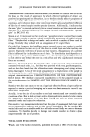
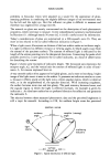
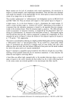
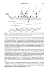
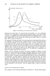
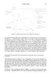
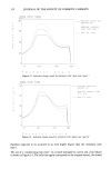
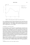
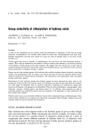
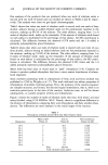
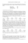
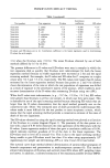
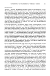
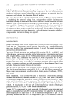
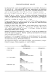
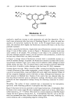
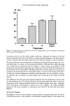
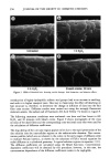
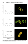
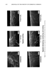
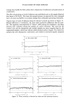
HAIR GLOSS 3O3 Major reasons are the lack of correlation with visual experiments, the restriction in respect to certain samples, and complicated instruments. Now and then new attempts were made: for example, in the standard ISO 10 216, where gloss is characterized by the clarity of an image seen on the sample (13). The so-called "glossmeters" or "reflectometers" are widespread, such as in ISO 2813 (6) and ISO 7668 (14). They are shown with respect to their optical layout in Figure 3. A light source, G, in the focal distance to lens L• illuminates the tested sample, P, under a certain incident angle, ½•, between 20 ø and 85 ø, depending on the purpose. It is assumed that the indicatrix maximum is located in the specular direction symmet- rically to the incidence beam. Here the receptor angle ½2 equals ½•. The reflected light, scaled as luminance or luminous intensity, is integrated by the photometer head con- sisting of a photoreceiver, E, situated in the focal point of lens L 2. The angular region near the specular direction 2•2, which is integrated, is adjusted by a diaphragm, B. Two examples are given in Figure 4, where the borders of the adjacent regions are located at ½• + • and ½2 -+ 13, respectively. The result is normalized by referring to a highly polished black glass and then expressing a "reflectometer value" or "specular gloss value," R' (½ •) and R' (½ •), respectively. These types of instruments are restricted to samples with an even surface and only little reflection from the bulk. But hair behaves differently from paint and the metal surfaces for which the gloss meters are mainly standardized. Figure 5 represents a simplified optical model for the reflection of light by a hair fiber, showing several possible directions for an indicatrix maximum. It only indicates the refraction and neglects scattering effects. A hair fiber can reflect light symmetrically to the incident direction when a cover of spray or liquid on the cuticle smooths the hair surface (ray A) or when reflecting facets in the cortex center are oriented parallel to the macroscopic hair fiber (ray B). G L• Figure 3. Scheme of a standardized reflectometer for estimating specular gloss acc. ISO 2813 or ISO 7668.

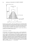
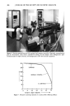
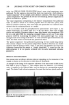
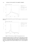
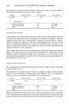
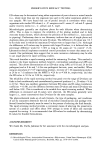
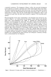
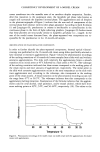
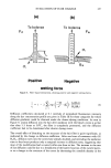
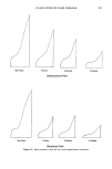
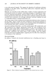
304 JOURNAL OF THE SOCIETY OF COSMETIC CHEMISTS luminanee. luminous intensity maximum reflectometer value •'[•) A •' [•) I oe1 oe1-d oe, +d oe1-• oe1+• Figure 4. Parametric characterization of a scattering indicatrix. half-value angle receptor angle But there are other possibilities. Light may be reflected by the cuticles before entering the hair, and because these cuticles are tilted against the fiber axis, the orientation of the main reflection direction is also tilted (ray C). If the light has the chance to pass the whole hair, a reflection at the opposite lying cuticles may occur (ray D). They are tilted in the opposite direction and therefore cause an opposite tilt of the reflected light. To measure the reflection maximum in all these cases, it is useful to move at least the photometer head in different receptor angles ½2. GONIOPHOTOMETER--PROPERTIES For this purpose, a more universal instrument is necessary, a so-called goniophotometer. In a basic version it is standardized as "abridged goniophotometer" in ISO 7759 (15). A precise computer-controlled instrument is shown in Figure 6 and explained more in detail in reference 16. The mechanical parts were designed and supplied by the Halle Company, Berlin the optical and electronic ones were purchased from several sources and assembled in BAM (Federal Institute for Materials Research and Testing, Berlin). This instrument was used for our research on hair gloss. The fixed horizontal arm carries the equipment for illuminating the hair sample on the central turntable. The illumi- nated part of the hair is nearly circular, with an area of about ! cm 2, and the incident angie ½• is variable (- 75 ø • ½• • + 75ø), but for better comparison with published data (2) for all measurements, ½• = + 30 ø was choseq.
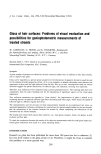
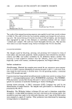
Purchased for the exclusive use of nofirst nolast (unknown)
From: SCC Media Library & Resource Center (library.scconline.org)