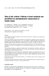
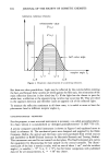
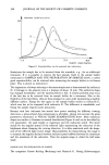
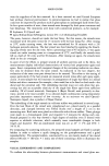
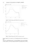
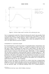
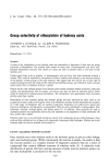
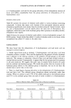
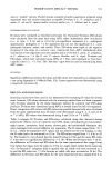
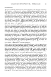
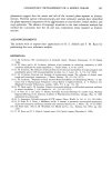
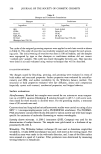
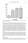
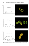
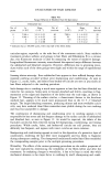
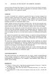
HAIR GLOSS 305 Figure 5. Possible directions for maximal reflection of light by hair. Ray A: reflection by a smoothing substance, covering the hair ray B: reflection by a cortex cell ray C: reflection by a cuticle before light enters the fiber ray D: reflection by a cuticle before hight leaves the fiber. The other arm, seen behind the turntable, has a horizontal working region (horizontal receptor angle) of about 180 ø and a vertical one (vertical receptor angle) of about 90 ø, but most hair indicatrices are measured in the horizontal plane only, the optical inci- dence plane (see CHARACTERIZATION OF THE PHOTOMETRIC DATA below). Therefore, if not otherwise indicated, the vertical receptor angle is fixed at 0 ø, and the receptor angle given in the figures is identical with the horizontal receptor angle. The movable arm carries the photometer head, the main equipment for detecting the re- flected light. It simulates a person who moves around the hair sample and evaluates the gloss from different points of view. When measuring corresponding hair indicatrices, conformity with natural conditions for gloss evaluation is important--for example, with respect to the illumination. Because the angular diameter of the sun as a natural light source is about 0.5 ø (17), a similar size for the chosen light source was chosen. Then an exclusively specular reflecting sample generates an indicatrix according to "a" in Figure 2, with a half-value angle of 0.5 ø (see CHARACTERIZATION OF THE PHOTOMETRIC DATA below). Therefore, no indicatrix details smaller than 0.5 ø can be resolved. When measuring hair strands, the chosen angular resolution of about 1 ø results in neglectable errors. The angular resolu- tion is limited by the mechanical parts of the goniophotometer and reaches 0.01 ø at its best. According to the section VISUAL GLOSS EVALUATION, the luminance, L, is used as a substitute for the visual brightness stimulus. To measure luminance the goniopho- tometer has to be calibrated with BaSO 4 as a good approximation of an ideal diffuse- reflecting surface. It is also illuminated under ½• = 30 ø.

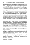
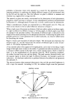
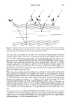
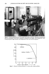
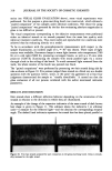
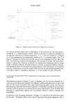
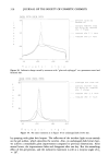
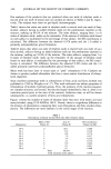
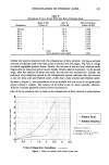
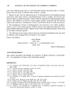
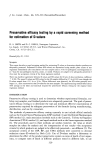
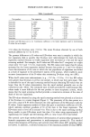
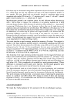
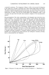
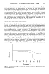
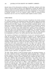
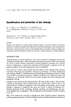
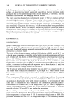
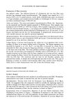
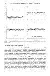
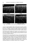
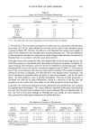
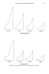
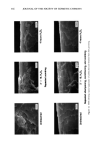
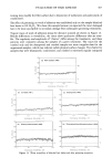
306 JOURNAL OF THE SOCIETY OF COSMETIC CHEMISTS Figure 6. Precision goniophotometer fully equipped and computer controlled. Right side: optomechanical parts for illumination center (front): turntable for holding the hair sample center (background): opto- mechanical parts for light detection left (background): shelf with electronic equipment. 552 -• ---lurn /,60 i 368 lurnin 276 - 18/, 92 t no definifio"/ -5 +9 +23 +37 51 65 79 recepfor angle / degrees • Figure 7. Measured scattering JndJcatrix of a nearly perfect reflecting diffusor.
Purchased for the exclusive use of nofirst nolast (unknown)
From: SCC Media Library & Resource Center (library.scconline.org)