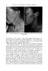
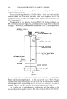
THE FLOW GAS CELL•AN INEXPENSIVE GEIGER-MUELLER DETECTOR By M. F. NF•so•, JP,.* ASSAY of radioisotopes on living tissue such as skin is often me- chanically very difficult to accomplish and sensitivity with end window Geiger tubes is generally only fair when carbon-14 or sulfur-35 is used. Tritium-tagged compounds are not detectable at all unless the trace ma- terials are mechanically removed from the tissue, or the tissue is converted chemically so as to give tritium in a gaseous or liquid compound suitable for ion chamber or liquid scintillation counting. Correlation of repetitive radioassays on living tissue becomes even more complex since reproducible geometry of the detector with the counting surface is a necessity. A flow gas cell was devised several years ago to overcome these difficulties and was described briefly in the literature (1, 2). This detector was used for the assay of carbon-14, sulfur-35 and tritium-tagged comp9unds on human and animal skin. Continued interest in the detector and inquiries concerning its construction have resulted in this brief publication. The flow gas cell is shown in Fig. 1. Although the diameter of the shell (which serves as the cathode) can be varied beyond the limits shown, it is important to remember that those characteristics desired in these types of detectors (especially good sensitivity and a reasonably fiat Geiger-Mueller Plateau) are influenced by the ratio of the diameters of cathode to anode. An improperly designed detector having an excessively large or small ratio can fail to function in the desired manner. The length of the detectors made and used by the author have generally been fixed at five inches (about 12.5 cm.), since this appears to be the most convenient length to use and gives satisfactory results. The anode is made from platinum or copper wire soldered into the tip of the coaxial fitting. Copper wire has been used most extensively since it is more rigid in use, although some cells made with platinum anodes have per- formed very well. In the interest of safety the anode length is made ap- proximately a/4 inch shorter than the length of the cathode so that when mounted the end containing the glass ball will be no closer than 1/,. inch * Atlas Chemical Industries, Inc., Chemical Research Department, Wilmington 99, Del. 125

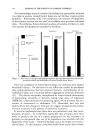
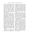
126 JOURNAL OF THE SOCIETY OF COSMETIC CHEMISTS from the bottom of the detector. This is to decrease the probability of ac- cidental electrical shocks. The coaxial fitting shown is a SO-239 which is best used with smaller coaxial cables, but cells have also been made with Amphenol 82-515 or Amphenol 82-504 fittings when larger coaxial cables, such as RG 8, 9 or 11/U were used (3). The gas used in the detector is either 99.05/0.95 helium-isobutane or 98.7/1.3 helium-butane Q gas mix, and the direction of gas flow is indicated in Fig. 1. In practice, a rubber tube is attached to the 1/4 inch copper out- AMPHENOL. 80' FOR R•58, 59 MOUNTING SCREWS ON END I/4" TUBING, •,/6"- I/2" TO 15 MIL PLATINUM OR COPPER WIRE ANODE I/4 "TUBING, 3/6" I/2"LG, I", I I/2' OR 2" COPPER TUBING 1/16" THICK GAS FLOW DISCARD THIS PART Figure 1. put tubing (at the top of the detector) and is connected to a small bubbler filled with diisobutyl phthalate. In this manner the rate of flow of Q gas can be noted and controlled, and the cell in use can be immediately checked for leakage when it is placed against the surface to be assayed. (A lack of bubbles shows a lack of continuity of gas flow and indicates a leak.) An airtight seal is made between the detector and the surface to be assayed by a rubber gasket shown in Fig. 1 and made as follows: A "Davol"
Purchased for the exclusive use of nofirst nolast (unknown)
From: SCC Media Library & Resource Center (library.scconline.org)