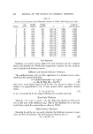
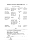
RHEOLOGICAL STUDIES AND PRODUCT FORMULATION 441 Table I Shear Rates of Cosmetic Interest Operation Assumptions Rate of Shear (sec -•) Source Roller milling Roller milling (2 rolls) Colloid milling Rollers 0.009 cm apart 10 • to 1.2 x 10 • Rollers 0.009 cm apart 1.2 x 10 • Speeds of 167 and 55 c•n/sec Forcing through Equivalent to crude hypodermic syringe homogenization Topical application Velocity of 10 cm/sec Layer of 0.1 cm Layer of 0.01 cm Layer of 0.001 cm Pouring from a bottle ... Aspiration of a plastic spray bottle Passage through an aerosol valve Extrusion Applying paint by brush Application of lipstick Small nasal tip Several hundred thousand 10 ß 10" 10 a 10 4 53 100 2 x 10 • 10 a to 10 * Liquid cream from plastic 10 bottle-Flow 1 cm3/sec, orifice i cm Toothpaste from metal tube 10 '• Flow i cm3/sec, orifice 0.5 cm Makeup from plastic tube 103 Flow 0.1 cm3/sec, orifice 0.1 cm 5 x 10³ to 104 2 x 10³ - 104 Sheman (7) Henderson (8) Henderson (8) Henderson (8) Sherman (7) Sherman (7) Henderson (8) Henderson (8) Sherman (7) Sherman (7) Fink-Jensen (9) Kinney (10) Table II Estimated Shear Rate Employed during Lipstick Application A. Surface Area Measurements 1. Testers were asked to blot lips after lipstick applications. 2. A planimeter was then employed to calculate the surface areas involved. 3. The mean surface area was estimated at 10 cm'/tester. 4. The mean application rate v was 10 cm/sec. B. Thickness of Lipstick Layer 1. Lipstick samples were weighed before and after single applications. 2. The mean lipstick weight applied per tester was determined as 0.05 g. 3. The density assumed for each formulation tested was approximated as being equal to i g/cm 3. 4. From the information given above, the thickness x of the applied lipstick layer was estimated as 0.005 cm. C. q/ shear rate = v/x q/= 10 cm/sec 0.005 cm q• = 2000 see -•

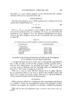
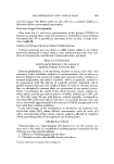
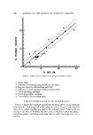
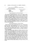
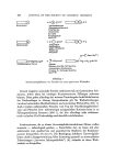
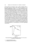
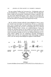
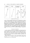
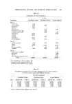
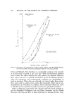
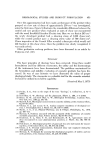
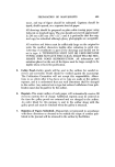
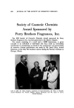
442 JOURNAL OF THE SOCIETY OF COSMETIC CHEMISTS BR00KFIELD BR00KFIELD BROOKFIELD/WELLINGTON ROTOVISC0 SYNCHR0-ELECTRIC T-BAR • ROTOVISC0 CUP • BOB CONE • PLATE BOB OTATING / •i' /,,'•/• /h'11 • • %'11 PLAT• CUP Figure 3. Viscometer geometry viscosity. With the Brookfield/Wellington and the Haake Rotovisco, absolute values are obtained. Details of the equations and calculations involved are available in a paper by Sherman (11). These calculations are reasonably com- plex. In our work, the Brookfield/Wellington calculations have been pro- gramed with an 1800 IBM Computer. Note that with the conventional Brookfield Synchro-Electric, there is no sharp definition of the wall of the containing vessel. The instrument is standardized to read NewtonJan fluids using a particular beaker as the containing vessel. When working with non- Newtonian systems, it is impossib]e to obtain accurate values in absolute viscosity. This can be done with the Brookfield/Wellington or Haake Roto- visco. COMPARATIVE VISCOMETRY In order to illustrate the utility and limitations of each instrument, three model formulations of varying types for rheological study have been pre- pared.* Products include an emollient cream, an emollient lotion, and a liquid makeup. All are taken directly from the most recent edition of Sagarin (12) and are shown in Table III. As lnuch as practical, all products were manufactured and studied under standardized conditions, particularly with respect to aging history. Table IV shows the results of a series of determinations made on these formulations with the Brookfield Synchro-Electric and the Brookfield with *Readings taken after 10 sec at cited rpm values.
Purchased for the exclusive use of nofirst nolast (unknown)
From: SCC Media Library & Resource Center (library.scconline.org)