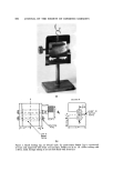
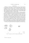
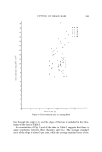
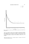
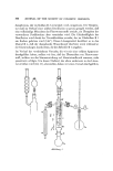
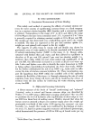
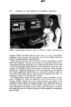
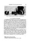
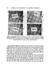
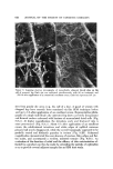
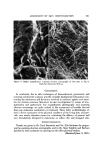
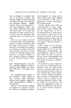
CUTTING OF BEARD HAIR 5S1 EXPERIMENTAL Preliminary investigations involved selection of the most useful geometry for cutting fibers. Anvil cutting, i.e., forcing a blade through a fiber, placed on a compression cell of an Instron• tester,* was found to require very precise positioning of the blade to prevent premature contact of the blade with the cell. Catchary cutting, i.e., pulling a blade through a fiber held firmly at both ends, but without any tension, was found to produce scraping along the fiber before cutting unless the blade was centered exactly. The method finally selected was cantilever cutting in which the beard fiber is allowed to protrude through a hole from the face of a brass jig (Fig. 1) placed on the crosshead of an Instron tester. The jig consists of a brass face, into which a 0.010-in. i.d. syringe tube bushing was inserted, and a set of rubber rollers to advance the fiber rapidly between cuts. The cutting blade was placed in a stirrup which was hung from the low range transducer (full scale 2 to 50 g) of a model TM Instron Tester. The fiber is cut by movement of the jig relative to the stationary blade. The angle between the blade and the face of the jig is approximately 3 degrees in order to prevent the blade froin moving away from the face of the fixture. During and between cuts, the fibers were maintained "in" the solution of interest by pumping the solution from a constant temperature bath through a capillary pipette which directed the stream onto the fiber and into the syringe tubing in the face of the fixture. The blades were randomly selected from one production lot of double edge (a) (b) Figure 2. Typical cross sections of (a) beard and (b) head fibers I I 0.1 mm *lnstron Corp., Canton, MA.

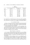
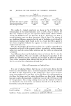
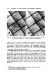
589. JOURNAL OF THE SOCIETY OF COSMETIC CHEMISTS Schick :blades coated with Vydax©* and were discarded after 5 to 10 cuts. No effort was made to examine or control variations in honing from blade to blade. Since only a few cuts of one fiber were made with each blade, and since these cuts occurred randomly over a distance of several millimeters along the blade edge, blade damage due to cutting was assumed to be mini- mal and neglected. The TM Instron Tester recording system was used for measuring the cut- ting forces at speeds up to 5 in./min. A Tectronix©* storage oxcilloscope (Model RM564) fitted with a strain bridge was used to measure forces at cutting speeds up to 50 in./min. By combining both methods, cutting forces were measured at speeds ranging from 0.1 in./min to 50 in./min. The use of scalp hair as a model for beard hair proved unacceptable, since the diameter of scalp hair is appreciably smaller and the cross-section much more regular than that of beard hair. Cutting force measurements in our labo- ratories demonstrated conclusively that scalp hair requires less force-to-cut (f-t-c) than beard hair. This may be merely a reflection of the fiber diameter or may be the result of the unexpected irregularity ,of beard hair cross-sec- tions as shoavn in Fig. 2. Although Hollander and Casselman (1) reported that white beard fibers are more difficult to cut than dark fibers, it was found here that the presence or absence of melanin had no effect on the f-t-c. The majority of the fibers used in this study were plucked from the beard of one subject. However, this was done only after comparing these fibers with those of four other volunteers and ascertaining that they were represen- tative of beard fibers in general. All chemicals used were analytical reagents except in the case of deter- gents, which were of commercial quality. PtESULTS AND DISCUSSION f-t-c versus Cross-sectional Area Beard fibers removed by plucking from 5 subjects were completely hydrat- ed and then cut 10 times at a rate of 0.5 in./min, while a stream of water at about 25øC was played on the fiber in the jig. The snippets created by the cuts were less than 1 mm long, and beard fibers as short as 3 cm suffice to yield statistically meaningful data. After each cut, the cross-section of the freshly cut surface was established by quickly photomicrographing the fiber in the jig and then determining the area with a planimeter. A plot of the f-t-c against the cross-sectional area is not very revealing (Fig. 3). Nevertheless, the slope for each fiber was determined by a linear regression analysis which forces the *Vydax is a registered trademark of the E. I. du Pont Co., Wilmington, Del. tTectronix Inc., Beaverton, Oregon.
Purchased for the exclusive use of nofirst nolast (unknown)
From: SCC Media Library & Resource Center (library.scconline.org)