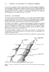
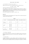
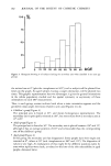
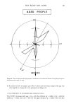
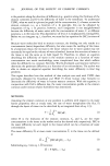
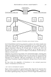
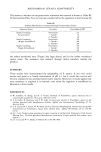
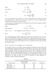
178 JOURNAL OF THE SOCIETY OF COSMETIC CHEMISTS are the same ones applied in surface engineering for measuring roughness, amplitudes, and wavelengths. Making positive replicas and numerous scans of surface profiles are time consuming. Recently, a new method using an image processing system was reported (4). We used this technique to study aging mechanism with cutaneous microtopography on 116 people from age 2 to 98 years. MATERIAL AND METHODS We chose the method described by Makki et al. (1) to obtain negative Silflo © replicas on a circular patch test of 15 mm internal diameter. A small tongue is used as a mark for alignment with respect to the body axis. Each sample (replica plus adhesive) is glued to a black metallic holder which ensures that the field to be analysed is plane. The holder is then inserted in a rotatory system graduated in degrees and centered under the plumbicon head of a Quantimet © 720 (Cambridge Instrument Co.). With a 55 mm lens a magnification of fifteen times is obtained on the TV display. Incident lighting of the replica with two floodlights generates shadows behind the furrows. These shadows are detected by their grey level. The incident lighting is opposite to the video scan direction, so intercept lines, corresponding to the horizontal projection of all detected areas, are superimposed on wrinkles and reproduce them. Field boundaries are fixed by a centered circular frame of 300 pixels in diameter. With Axsl • LIGHTING _AXS 2 Figure 1. Schematic representation of the negative skin relief and basic principle of the Image Analysis Method.

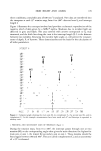
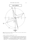
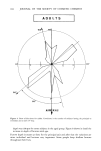
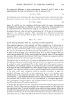
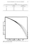
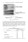
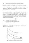
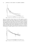
SKIN RELIEF AND AGING 179 these conditions, a total skin area of 100 mm 2 is analyzed. Two data are transferred into the computer at each 15 ø rotation step, from 0 to 36Oø: detected area Sd and intercept length I. Figure 1 illustrates the concepts involved and provides a schematic reproduction of the negative relief of skin given by a Silflo© replica. Shadows due to incident light are detected in grey and black. The area covered with arrows corresponds to Sd truly measured, and the thick line along the crest is the intercept length (I). L is the distance between two wrinkles. Knowing the incident light angle, o•, will permit the measure- ment of depth, P, of furrows. These determinations are the basis for the calculation of all other parameters. 228 M2 • C1 Figure 2. Computer graph showing the main axis M•, its complement C•, the second axis M2, and its complement C2. In this example, rneasurements have been made each 9 ø and Intercept is expressed in arbitrary units. 1. PRINCIPAL AND SECONDARY AXES OF WRINKLES (Figure 2) During the rotation steps, from 0 to 180 ø, the intercept passes through one or two maxima (M), so the corresponding angle value gives the main direction: the highest for main axis or axis 1, the lowest for secondary axis or axis 2. These maxima should be found again between 180 and 360 ø. They are called complements (C), and an asymmetry of + 15 ø •s tolerated.
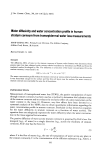
Purchased for the exclusive use of nofirst nolast (unknown)
From: SCC Media Library & Resource Center (library.scconline.org)