QUASI-STATIC TORSIONAL DEFORMATION OF SINGLE HAIR FIBERS 385 at the outer surface because of a fourth power relationship between torsional stiffness and fi ber diameter. For a circular, symmetrical cylinder, there is no change in cross-sectional shape as a torque is applied, which results in the shear stress being uniformly distributed along the fi ber’s outer surface (11). In reality, hair fi bers do not exhibit a perfect circular cross section but a more elliptical cross-sectional shape, which complicates matters. This elliptical nature results in a warping effect of the fi ber cross-sectional plane as it is twisted with the maximum shear stress acting on the outer edge of the fi ber, where the maximum arc length displacement of twist angle exists (10,12). This produces a maximum peripheral shear strain at the minor axis and points along the fi ber’s outer surface (10,12). Since the shear stress is at a maximum at the periphery of the fi ber, the torsional modulus may be signifi cantly infl uenced by the outer layers of the fi ber, particularly by the cuticles (6). This has been experimentally demonstrated by Masaaki et al. (13), where the torsional modulus was measured on hair fi bers with intact cuticles and where the cuticle layers had been removed. With the intact cuticle fraction, the fi bers were found to have a torsional modulus of 0.795 GPa, whereas when the cuticles were removed, the modulus decreased to 0.430 GPa, concluding that the cuticle makes a signifi cant contribution to the torsional modulus. A similar deduction was made by Harper and Kamath (14), who observed a substantial reduction in the torsional modulus when the surface of the hair was abraded as a means of removing the cuticles. Early work investigating the torsional deformation of keratin originated within the wool industry and focused on using variations of the pendulum method (15–19). These ap- proaches have since been adopted in the cosmetic industry to measure torsional properties of hair fi bers (12,14,20–23). The pendulum method involves suspending a weighted bob from one end of a fi ber, twisting the fi ber, usually through 360°, and then setting it off into free rotational oscillations. The frequency and the magnitude of the oscillations are measured, from which both the storage and the loss torsional moduli can be calculated. Despite the simple design of the pendulum method, there are a number of shortcomings. The method lacks automation and the pendulum bob needs to be manually attached to each fi ber specimen, resulting in a time-consuming and labor intensive operation, which limits the sample sizes that can be run. In addition, the pendulum method is an indirect measurement of the torsional storage modulus. Bell et al. (6) conducted studies to com- pare the torsional storage modulus of nylon and hair fi bers using both a pendulum method and the Dia-Stron FTT950 automated system (Dia-Stron Ltd., Andover, UK), which directly measures the torsional modulus. The results indicated that whereas both the indirect pendulum and direct automated methods provided both a consistent and reproducible measurement of the torsional modulus, the direct measurement method appeared to offer improved repeatability and higher testing throughput. The Dia-Stron FTT950, Fibre Torsion Tester (Dia-Stron Ltd.) is an automated system which enables the direct measurement of the torsional properties and subsequent stress relaxation of fi bers. The system is used alongside the Dia-Stron FDAS770 (Dia-Stron Ltd.) to measure fi ber dimensional properties and in conjunction with the automated loading system, allowing high-throughput measurements of the torsional properties of fi bers. Fibers are mounted between two plastic tabs, giving a gauge length of 30 mm. Either before or after dimensional measurements, a central plastic torsion paddle is attached. This paddle has a length of 14 mm, which generates two equal test sections of the fi ber with lengths of 8 mm. The two ends of the fi ber are rotated at a user-defi ned angle, synchronously

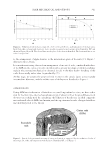
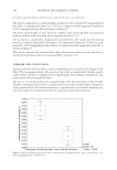
JOURNAL OF COSMETIC SCIENCE 386 at a constant angular rate so that the central paddle moves against a fi xed microbalance, which is incorporated into the measurement module (Figure 2). Based on that instrument principle, the resulting torque τ can be calculated by equation (1): τ = FL, (1) where F is the force (N) applied onto the stainless steel pin of the microbalance and L is the arm length of the pivot paddle from the fi ber to the pin (m). The Dia-Stron UvWin software (Dia-Stron Ltd.) determines the torsional modulus G from the cross-sectional measurements of the fi ber. The UvWin software analysis func- tion calculates the torsional rigidity constant D using equation (2): D = π 3 2 , +b2 a b3 a (2) w here a and b are the radii of the major and minor axes, respectively. The torsional mod- ulus G can be calculated as follows by using equation (3): șD = , FLl G (3) wh ere G is the shear modulus (Pa), F is the force measured by microbalance (N), L is the distance of fi ber pivot from microbalance (m), D is the torsional rigidity constant (m4), θ is the angular rotation (radians), and l is the fi ber length (m). Fig ure 2. Principle of operation of direct torsion method, where F is the applied force at a moment arm length L and θ is the angle of twist.
Purchased for the exclusive use of nofirst nolast (unknown)
From: SCC Media Library & Resource Center (library.scconline.org)