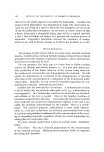
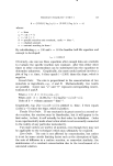
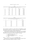
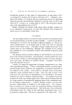
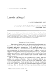
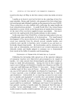
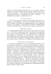
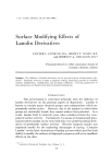
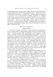
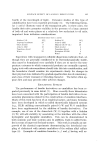
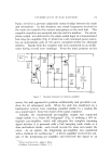
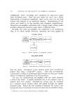
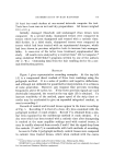
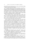
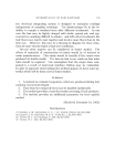
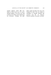
DETERMINATION OF HAIR RASPINESS 173 frame, served as a pressure adjustable contact bridge between the comb and microphone. In this situation, any sound frequencies received by the comb are carried to the contact microphone via the steel bolt. This complete assembly was mounted onto the end of a minibox. The micro- phone output was delivered to the single-ended input of a transistorized four stage pre-amplifier (Fig. 2) which has a self-contained power source, has an approximate gain of 100 and is contained within the aforesaid minibox. Signals from the complete unit were monitored on an oscillo- scope during several tress combings. From the noise patterns on the •.•v I I I T 5•u m,n. I I _L •2v / e ect. I I q.. ,rmn. / •___• t•,l, I / e•ec• / •1' 68• J I -' I Mallory .680a I00 K T• C •)Out Figure 2. Diagram schematic of comb pre-amplifier screen, the unit appeared to perform satisfactorily and provided a nu- cleus for all subsequent work. When the unit was monitored on a loudspeaker system, tress combings sounded similar to a rasping file on a sound board hence the choice of the name, raspiness. Initially, the transistorized pre-amplifier output was connected (single-ended) to a Grass 5B Polygraph* (Fig. 3) utilizing a 5P3 in- tegrator pre-amplifier, which will integrate the complete incoming signal whether it is procured with a fast sweeping comb stroke or a slow methodical stroke each record reveals the same area under the curve. As an option, the integrating pre-amplifier was monitored with a DuMont 411 oscilloscope. t A driver amplifier received the out- put of the integrating pre-amplifier and delivered the signal to an * Grass instrument Co., Quincy, Mass. i DuMont Laboratories, Clifton, N.J.

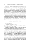
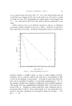
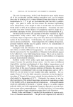
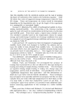
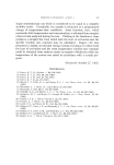
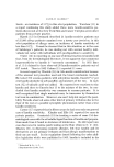
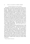
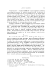
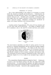
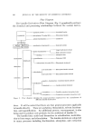
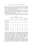
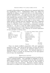
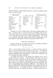
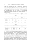
174 JOURNAL OF THE SOCIETY OF COSMETIC CHEMISTS oscillograph, where recordings were produced on strip-chart paper with curvilinear pens. Since the area under the curve has a direct relationship to frequency amplitude, chart curves were cut out with scissors and weighed on an analytical balance. Planimetering of the curves was found to be less accurate and, therefore, unsatisfactory. Integrator pre-amplifier calibration with a known input voltage makes possible comparisons between results taken at different times. Secondly, the comb pre-amplifier was connected to an oscilloscope (Fig. 4) to which outside electronic capacitors had been applied to POLYGRAPH METHOD TRANSISTOR I I INTEGRATING I I DRIVER I I I PRE-AMPLIFiERI [ II I [ I OSCILLOSCOPE Figure 3. Block diagram of polygraph method OSCILLOSCOPE METHOD mE-AMPLIFIERJ I I I I m I Figure 4. Block diagram of oscilloscope method slow the sweep. Deviations of the electron beam were recorded on positive film using a Polaroid©* camera. After film development, a photometer reading of transmitted light through the film gave results relative to deflection amplitude of the electron beam. For use, the transistorized pre-amplifier with the comb attached is held in the hand. A rigidly mounted tress or the subjeet's hair is combed with even strokes. Alternatively, tresses may be mounted on a constant speed rotating wheel and pulled through the rigidly mounted comb. Before the test combing is initiated, the comb is run through the hair several times to ensure no snarls and to establish timing. * Polaroid is a trade mark of Polaroid Corp., Cambridge, Mass.
Purchased for the exclusive use of nofirst nolast (unknown)
From: SCC Media Library & Resource Center (library.scconline.org)