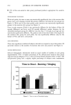
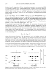
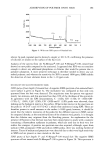
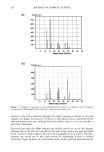
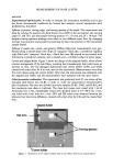
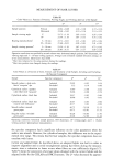
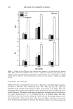
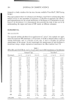
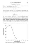
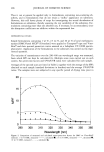
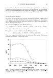
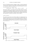
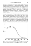
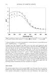
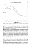
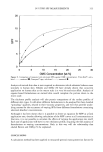
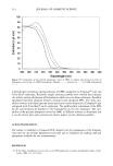
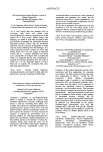
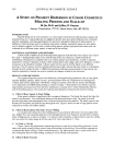
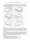
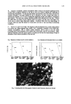
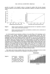
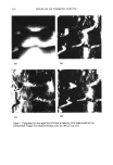
324 JOURNAL OF COSMETIC SCIENCE A STUDY ON PIGMENT DISPERSION IN COLOR COSMETICS: MILLING PROCESS AND SCALE-UP Di Qu, Ph.D. and Jeffrey W. Duncan Amway Corporation, 7575 E. Futon Street, Ada, MI 49555) INTRODUCTION Pigment dispersion in color cosmetics is a critical aspect which directly affects product quality and manufacturing cost. Typical pigments are supplied in powder form and contain different sizes of primary particles, aggregates, and large agglomerates that need to be adequately dispersed in final products. In addition to chemical means such as surfactants and surface coatings, mechanical means are also widely used to disperse pigment. In this study, a batch milling process using a high-speed rotor-stator mill was evaluated at two different setups, namely in-tank and in-line milling. MATERIALS, EQUIPMENT AND METHODS Commercially available oil and water dispersible pigments (red and black iron oxides) were used in this study. A hydrogenated jojoba oil (in colored beads form) was chosen as a model material for establishing milling process conditions due to its uniform particle size distribution. A batch is typically prepared by mixing 1% pigment or beads, 0.04% sodium lauryl ether sulfate, and 0.01% defoamer, in either an aqueous or an anhydrous medium. A Rotor-stator mill was used to mill the batch in two different processes. The first process involves milling a batch inside a tank, whereas the latter refers to recirculating through the mill outside the tank. A FBRM (focused beam reflectance measurement) in-line particle size analyzer supplied by Lasentec was used to monitor the changes in particle size and count. RESULTS AND DISCUSSION The pigment dispersion process was affected by several processing parameters such as rotor speed, impeller pumping capacity, batch viscosity, and recirculation flow rate. Experiments were designed to evaluate each of these parameters individually. Changes in particle count and size (mean chord length) were captured by the FBRM during milling, as shown in Figure 1. Mean particle size and the count for large particles decreased over time until they stabilized at a constant level, which indicated the effective end of the milling process. The counts for total and small particles increased as the result of milling. A. Effect of Rotor Speed: In-Tank Milling Rotor speed exhibited a significant effect on pigment dispersion. The higher the speed, the faster the particle size decreases. Two contributing factors are tip speed and turnover rate. Tip speed of the mill provides high shear and impingement force, which act to break down the particles. The batch turnover rate dictates how frequently the particles pass through the mill. Figure 2 shows the rate of large particle count reduction at various mill rotation speeds. B. Effect of Recirculation Flow Rate: In-Line Milling At constant rotor speed, the in-line milling process was primarily affected by the recirculation flow rate. Higher flow rate caused the particles to flow through the mill more frequently and therefore yielded a faster milling process, as shown in Figure 3. To achieve a 60% reduction in large particle count, the milling time was about five times longer at the flow rate of 22.3 ml/s than that at 71.2 ml/s. C. In-Tank vs. In-Line Figure 4 shows the performance comparison between in-tank and in-line milling processes. At the same rotor speed, in-tank milling is much more efficient than in-line milling. The result also supports the conclusion that batch milling is a flow-controlled process. The batch turnover rate is much slower for in- line milling than that of in-tank milling, resulting in a loss efficient unit operation. D. Effect of Batch Viscosity

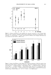
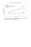
2000 ANNUAL SCIENTIFIC SEMINAR 325 Since batch milling is affected by flow properties, product viscosity shows a significant effect on this process. Reduction of large particles was about 3 times faster in a lower viscosity batch, as indicated by Figure 5. This result suggests that in order to achieve the same level of pigment dispersion, longer milling time is required in higher viscosity batches. Changes of Particle Size and Count dudng Milling as Measured by FBRM $000 l[•"'-•a.--'•- -'•--Z ........ TotalCount I 250 • 5000 } ...... % • ..... Count •149 mcro) • 200 • I Ml_ Mean Chd Lenth/ 4000 [ ---- ---- --• 150 100 50 0 0 200 400 600 u•. sec Figure 1 Effect of Recycle Flowrate on Parhcle S•ze Reducbon In-L•ne Milling at Constant RotorSpeed 12o lOO 8o 40 20 0 Effect of Rotor Speed on Particle Count Reduction In - Tan k Millin g 120 • 100 80 ,• • 60 4o • •o o Rgure 2 o 100 200 300 400 Tlrl•, sec Performance Companson In- Tank vs In- L•ne F•gure 3 200 400 600 800 Time, sec Effect of Batch Viscosity on P•gment Milling 80 4O 20 0 0 100 200 300 400 500 600 Ftgure 4 T•me, sec Effect of Batch S•ze on the Reqmred Milhng T•me • o 50 lOO Time, sec F•gure 5 lOOO 8oo 600 4OO 200 0 F•gure 6 ß In-Line - ß In-Tank - --- i Dnear 0n-Line) Linear (In-Tank) i 25 5O 75 1CO 125 150 Batch Slze,lb E. Scale Up A series of milling tests were conducted at various sizes of pilot plant equipment. While holding mill size and speed constant, a linear function is observed between batch size and milling time for both in-tank and in-line milling processes (Figure 6). This graph indicates that the milling time required to achieve a target milling level can be predicted by using the slope of the line calculated from lab or pilot test results. SUMMARY The results of this study indicate that the pigment milling process is generally affected by rotor speed and by batch turnover rate. Consequently, it is affected by product viscosity, mill arrangement (in-tank or in-line), and recirculation flow rate. Higher mill speed and better batch turnover rate reduce milling time significantly. Longer milling time is required for larger batch sizes. The FBRM in-line particle analyzer is found to be a very useful tool to collect real-time data necessary for the study. REFERENCES 1. T. Goldner, Cosmetics & Toiletries 101 (4): 91 - 94, 1986. 2. R. Johnson and A. Hodel, Chemical Processing 50 (11): 108 - 110, 1987. 3. H. Epstein, Cosmetics & Toiletries 110 (3): 83 - 89, 1995. 4. Lasentec, FBRM User Manual, Understanding & Utilizing FBRM, May 1998.
Purchased for the exclusive use of nofirst nolast (unknown)
From: SCC Media Library & Resource Center (library.scconline.org)