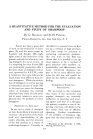
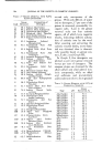
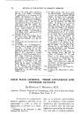
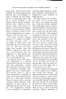
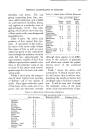
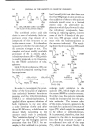
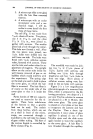
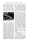
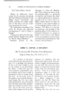
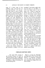
SWELLING STUDIES OF SINGLE HUMAN HAIR FIBERS 245 fiber swelling had shown that several characteristics are desirable in an apparatus for making reproducible and reliable measurements of hair diameters, while those diameters are continually changing. Quite obviously a microscope must be employed to observe the fiber dur- ing the experiment. For recording the changes in diameter in the course of an experiment the two most readily apparent means are photographically or by visual ob- servation. The latter method was chosen for several reasons. Any mounting device for the fiber which we could design would always al- low at least a slight lateral play which had to be corrected by visual inspection. Also, it is often found to be necessary to focus separately on the two edges of fibers which are not perfectly round. Photograph- ing the fiber would of course be a more accurate procedure if the other factors could be controlled, but visual observation has proved sufficient for our purpose up to this time. The most rigid specification for apparatus design is in the mount- ing of the hair fiber. The hair must be firmly anchored at one end, but not at the other. The reason for this is that the longitudinal swelling and deswelling of a fiber anchored at both ends will bow the fiber in and out of the field of view. How- ever, the free end must not be al- lowed to dangle loosely, since it would then drop out of focusing range when the fiber is softened by various solutions. Another feature which should be included is a means of changing the reagent in contact with the fiber. Changing of the solution must be quick and simple in order to avoid interfering with the timed read- ings. A means' of eliminating air and gas bubbles from around the fiber should be incorporated since these can affect the reaction of the solu- tion with the fiber and obscure the observation of the diameter. I believe that these requirements have been fulfilled in the apparatus to be described. The equipment for making swell- ing studies consists of: 1. A cell to contain the hair fiber and the reacting solution. Reagent reservoirs and a manifold system for admit- ting various solutions into the cell. Figure 1.'

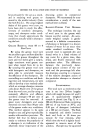
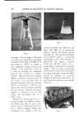
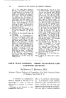
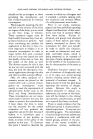
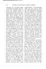
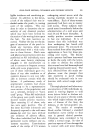
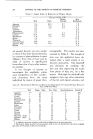
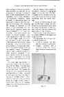
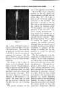
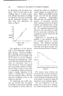
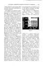
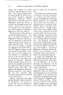
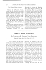
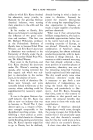
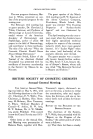
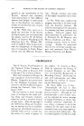
246 JOURNAL OF THE SOCIETY OF COSMETIC CHEMISTS 3. A microscope slide cover glass with the hair fiber mounted thereon. 4. A microscope with an ocular micrometer scale and a me- chanical stage. I will de- scribe in some detail the first three of these items. The cell (Fig. 1)was made from a,/•6-in. sheets of Lucite. Two pieces, one 3 X 11/16 in. and the other 11/2 X 11A• in., were joined to- gether with acetone. The smaller piece had a hole through the center. This hole now formed a well. After the two pieces were joined, two Vs-in. holes were drilled into the well from one side. The holes were fitted with 1/8-in. cellulose acetate tubes, fastened with acetone. These are the inlet and outlet tubes for re- placement of reagents. The upright elbow on the outlet tube inside the well insures removal of gas or air bubbles which would interfere with the experiment. The spring clips on the ends are used to hold in place the cover glass, on which the hair fiber is mounted. The hair fiber is of course on the under side of the cover glass so that it is inside the well Pyrex bottles of 500 ml. capacity are used as reservoirs for the re agents. These have tubulatures at the bottom so that a gravity feed can be used. The outlets from these bottles, which are set on a shelf in front of the micro- scope, are connected through a manifold to the cell inlet by means of gum rubber tubing. The flow of the various liquids is controlled by Mohr clamps (Fig. 2). ' :'•.":'i!½".. 7:-!" ' • : • :•m• 2:• i--' ' ......... • •,•.:'" .... .......... :.•:-:,,,,,...'• :•' ,k: '. • ' .•:•'. :.. _¾ : -'•.5•:• • .:x .... ::.: --. • ...... ........ :: ...... . •'.... ..? . •n•- .... . Figure 2. The manifold was made by join- ing two x/2 X l t/•-in. pieces of a/•o-in. Lucite with acetone, and drilling one l/8-in. hole through lengthwise and four x/8-in. holes in from one edge. Short pieces of cellulose acetate tubing were fast- ened in the six holes with acetone. Figure 3 is a low magnification photomicrograph of a mounted hair fiber, which is prepared by the fol- lowing procedure: two drops of a 5 per cent Vinylite solution in acetone are placed on a 20 X 40-ram. thin slide cover glass. The cover glass is placed on a hot plate at 19w heat to evaporate the acetone and fuse the Vinylite. Then a short (ap- proximately 3 min.) piece of glass capillary is placed on one of the Vinylite spots and the slide cover again heated to bond the capillary to the cover glass. A hair fiber is now threaded through the capillary
Purchased for the exclusive use of nofirst nolast (unknown)
From: SCC Media Library & Resource Center (library.scconline.org)