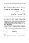
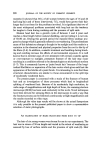
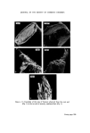
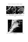
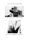
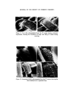
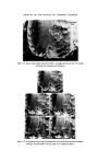
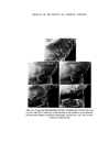
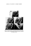
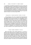
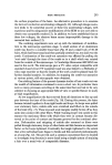
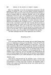
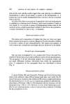
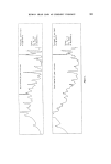
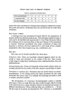
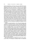
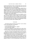
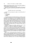
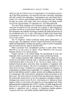
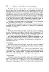
HAIR BREAKAGE 293 the surface properties of the hairs. An alternative procedure is to examine the hairs at low electron accelerating voRages (8, 12). Although image resolu- tion tends to be somewhat poorer at these low accelerating voRages, with experience and by using minor modifications of the SEM we are now able to obtain very acceptable results (13). In addition we have established that at these low voRages, the electron beam causes imperceptible damage to the uncoated hair surface (13). The combing experiments were set up with the minimum of modifica- tion to the microscope specimen stage. A small section of an aluminium comb was fixed to a suitable brass base (Fig. 9) and a small lock of 30-40 hairs, which had been teased and then partially combed-out, was laid over the comb. Continuation of the comb-out operation was effected by pulling the 'root ends' through the tines of the comb on to a shaft which was rotated from the outside of the microscope. A Cambridge Stereoscan 600 SEM was used in this work. The microscope gave a TV video output compatible with standard closed circuit TV equipment and was also linked to a Shibaden «" video tape recorder so that the results of the work could be played back for further detailed analysis. In addition, by stopping the comb-out operation at various points, still micrographs were obtained. One striking feature of the present dynamic studies of hair comb-out was the wealth of information contained in even a short run. In particular there were so many processes occurring at the same time that one had to be very selective in choosing an appropriate field of view or specific feature to study at high magnification. At low magnification the hairs moved from all directions to line up and pass between the tines of the comb (Fig. 10). During this process, the hairs became twisted together to form tight bends and loops. As loops were pulled over stationary hairs, cuticle cells were stretched and lifted on the outside of the bend (Fig. 11). These exposed scale margins readily broke off as they came into contact with other fibres. While 'running loops' lost cuticle in this manner the stationary fibres with which they were in contact became dis- torted at the point of contact and became grooved by the continual abra- sion. Deformation and stripping of cuticle also occurred as fibres were pulled through stationary loops of other hairs and this became an important factor as the loops tightened. Eventually the tangle tightened to the extent that a few individual hairs began to break and this occurred predominantly at a loop (Fig. 12). This proved such a common occurrence that we decided to investigate loop fracture in more detail using a simple system of straining a hair over a metal wire of comparable diameter.

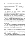
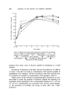
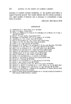
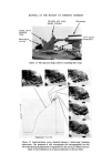
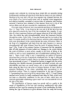
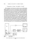
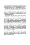
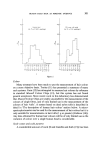
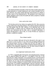
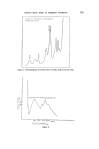
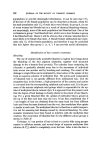
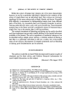
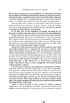
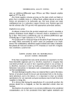
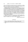
294 JOURNAL OF THE SOCIETY OF COSMETIC CHEMISTS EXAMINATION OF DYNAMIC 'LOOP BREAKS' IN THE SEM The investigation of loop breaks was carried out using a small extending specimen stage (Fig. 13). In one set of jaws the two ends of a short length of 100-gm diameter Constantan wire was clamped. Looped through this wire and attached at both ends to the other jaw was the hair under investigation. One jaw was fixed and the other was driven on a screw thread by means of a d.c. micromotor controlled from a power supply outside the microscope. The speed of separation could be varied from 1 mms 4 to 10 gm s 4, the lower speed being necessarily slow so that details of the fracture propaga- tion could be recorded at magnifications up to x 10,000. The fixed jaw of the stage carried four small semiconductor strain gauges arranged to measure the minute bending forces of the jaw support as load was applied to the loop under test. Output from the strain gauges was fed through an amplifier to a chart recorder so that at constant speed of extension a load/extension curve was obtained at the same time as the structural information was recorded on video tape (Fig. 14). In this way we have been able to relate small irregulari- ties in the load/extension curve to corresponding changes taking place in the SEM Strain J gauges Specimen stage Micromotor •ower supply Electron detector and photomultiplier Pen recorder recorder o o o o Figure 14. Block diagram of the equipment used in the 'loop-break' experi- ments.
Purchased for the exclusive use of nofirst nolast (unknown)
From: SCC Media Library & Resource Center (library.scconline.org)