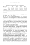
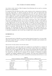
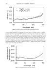
DEVICE TO MEASURE HAIR LUSTER 243 0.10 0.05 0.00 -0.05 -0.10 400 500 600 700 wave length [nm] Figure 8. Similarities among spectral reflectances. even when the measurement angle changed, it was concluded that the spectrum com- position was invariable. From this result, the conditions not being influenced by the wavelength and geometric parameter satisfied an important assumption of DRM. There- fore, it was verified that human hair can be described by DRM. INFLUENCE OF THE ARRANGEMENT ANGLE ON REFLECTANCE The reflectance characteristics in each arrangement angle of human hair were plotted in three-dimensional graphs, as shown in Figure 10. When the arrangement angles p of the O.OOO4 = 0.0003 • 0.0002 ß -• 0.0001 0.0000 400 500 600 700 wave length [nm] Figure 9. Standard deviation of the difference between reflectance and the average value.

244 JOURNAL OF COSMETIC SCIENCE 4oo receiver angle receiver angle 70 70 [deg] [deg] (a) p=O ø (b) p=45 ø 0.20 0.20 • 0.15 0.10 • 0.10 • 0.05 e 0.05 0'0•21 receiver •gle [deg] 70 •oo receiver •gle 70 [deg] (c) p =90 • (d) p = ]80 ø Figure 10. Spectral reflectance at each angle of hair. human hair were 0 degrees, 45 degrees, and 180 degrees, the peak of the specular reflection was seen at the receiving angle near 45 degrees. However, when the arrange- ment angle was 90 degrees, the peak of the specular reflection was not seen and the distribution became flat. The spectrum compositions at each arrangement angle when the receiving angle was 0 degrees are shown in Figure 11. The reflectance values at arrangement angles of 0 degrees, 45 degrees, and 180 degrees were almost identical, but about four times as large at 90 degrees. This result is believed to be due to the specular reflection mixed in various angles, as shown in Figure 12. For this reason, when the arrangement angle of the human hair is 90 degrees, the region of the diffuse reflection alone cannot be specified. Therefore, the arrangement angle of the hair needs to be considered in the case of device design. EXAMINATION OF THE OPTICAL SYSTEMS Each diffusion reflective composition for the two situations--when the receiving angle qb of the one light source/two receivers system was 0 degrees, and when the incident angle 0 in the two light sources/one receiver system was 0 degrees--are shown in Figure 13. The two results were almost congruous, which consequently showed that the same result was obtained by the two systems. Generally, to improve the accuracy of the measure- ment, the same parts need to be regulated. Since light source adjustment was easier than manipulating the receiver, the two light sources/one receiver system was adopted.
Purchased for the exclusive use of nofirst nolast (unknown)
From: SCC Media Library & Resource Center (library.scconline.org)