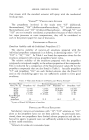
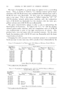
FORMULATING AEROSOLS TO OBTAIN SPRAY PATTERNS 293 • ACTUAORIFICE -•' ---•- - - DETAIL STE ORIFICE Figure 3. the propellent. With the same pressure in the container and the same valve, a formulation which discharges a streamy jet will deliver more grams per second than if the formulation were prepared to give a spray. This is due to the fact that a portion of the propellent is flashing to vapor before leaving the throat of the stem orifice of the valve, because the pressure there is lower than the equilibrium pressure in the container. Thus, the stream entering the actuator orifice is a mixture of liquid and vapor. Since the density of the liquid-vapor mixture is lower than the density of the liquid alone, the weight of the discharged spray is lower than of a liquid jet. The pressure at the throat of the actuator orifice is again lower than in the chamber between the stem and actuator orifices, and therefore, here again a portion of the propellent will flash. This secondary flashing does the main job of atomization of the product into small particles. It should be emphasized that the secondary flashing occurs at the throat of the actuator and, therefore, "exploding" of the liquid propellent cannot take place sideways of necessity, it must be projected foward in the shape of a cone. The flashing of a propellent is the main cause of disintegration of the liquid stream in an aerosol spray. It takes place not only on the circum- ference, but also throughout the whole throat area of the valve orifice. The expanding volume of the mixture accelerates the stream. The flashing promotes the detachment of liquid particles from the main liquid stream and assists in the disintegration process.

294 JOURNAL OF THE SOCIETY OF COSMETIC CHEMISTS How Muc• or PROPELLENT CAN FL^S•? If we omit the influence of other components in the aerosol formulation, and consider only the propellent, the percentage which will flash to vapor can be calculated easily from its thermodynamic properties. From the heat balance for the adiabatic process (at constant heat content), we obtain the equations: y_ ha-- hS0orY= C(t•-tø) (hs,)0 (hsg) 0 where Y = percentage of flashing propellent in B.t.u./lb. hfi = heat content of liquid at the initial pressure pi in B.t.u./lb. hs0 = heat content of liquid at the surrounding pressure P0 in B.t.u./lb. (hsg)0---- the latent heat of evaporation of the liquid at the surrounding pressure p0 in B.t.u./ lb. t• -- the initial temperature of liquid in øF. to = the equilibrium temperature of liquid at P0 pressure in øF. c = the average sr•ecific heat between t• and to in B.t.u./lb. øF. Based on the above equations, graphs were prepared showing the amount of propellent which will flash when exposed to atmospheric pressure from any initial temperature. These graphs are very useful in comparing certain important characteristics of aerosol formulations made with different propellents. Figures 4, 5 and 6 show the calculated flashing amount of some hydrocarbon and halocarbon propellents, and their mixtures. It is interesting to note that at 80øF., the amount of flashing propellent 114 is higher than the amount of flashing mixture of propellents: 75 per cent 11-25 per cent 12, although the latter has a higher vapor pressure. This effect explains why at 80øF., formulations made with propellent 114 have a finer spray than those with the above mentioned mixture of propellent 11 and 12 at a higher pressure. At low temperatures, however, this effect is reversed as the curve of flashing indicates. Our experience in production and in pre-testing of glass aerosols also con- Figure 4.--Flashing of halocarbon propel- lents (P) mixtures of P-11 and P-12. Figure 5.•Flashing of halocarbon propel- lents (P)mixtures of P-12 and P_114.
Purchased for the exclusive use of nofirst nolast (unknown)
From: SCC Media Library & Resource Center (library.scconline.org)