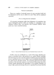
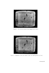
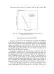
THE PARTICLE SIZE ANALYSIS OF PIGMENTS WITH THE QU•INTI•/IET 679 screen (Fig. 6). These pulses, each of which corresponds to a scan line crossing a boundary, are quantised. They may be integrated to provide a final read-out which is a measure of the projected boundaries of the features. For example in Fig. 6 the total projected boundary is equivalent to 2.2 times the vertical boundary of the blank frame. Once again this is known. By incorporating a memory into the system, a means is obtained whereby the particles may be quickly counted. This memory takes the form of a single scan line time delay. Thus, if one detected boundary is followed by another, it is forgotten. The last boundary pulse for any feature fails to trip the memory circuit, and a count pulse is emitted. These count pulses are presented on the monitor screen as "flags" (Fig. 7). They are also of equal magnitude and when accumulated give a total signal equal to the number of detected features. An electronic "gate" is also associated with the count circuit, by means of which the size of features may be determined. There are many definitions of (particle) size which will be found elsewhere (2,13). It is not an unequivocal term, but an operational concept which depends upon the method of determination and certain conventions regarding its definition. In the context of this application it refers to the maximum chord crossing the particle in the direction of scan. If this maximum chord is smaller than the equivalent 'size' of the gate, then the computer memory fails, and the feature is forgotten. The size of this gate is variable, and thus the number of particles greater than, or equal to, a specific size may be easily determined. The effects of the gate may be easily followed on the monitor screen (Figs. 7 and 8) for increasing gate size. Additional features are provided in the memory system to allow correction 1. to eliminate errors which arise from particles touching or overlapping, 2. to eliminate errors arising from the presence of re-entrant boundaries. These corrections are obtained by incorporating a small variable, additional delay to the memory (a single scan line time delay). This may be added to, or subtracted from, the memory so that unusual changes in the displacement of particle boundaries may be accommodated. However, from some points of view, this additional control is un- necessary. The degree of correction has been found to be insufficient for all boundary irregularities encountered. Also, both faults, which require opposite correction, occur together in the same sample.

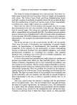
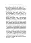
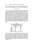
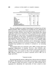
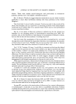
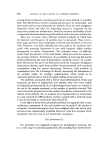
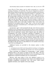
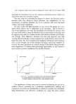
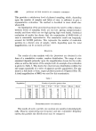
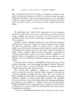
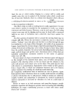
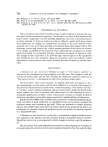
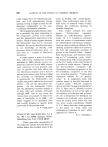
680 JOURNAL OF THE SOCIETY OF COSMETIC CHEMISTS Practical considerations There are a number of potential sources of error associated with both the instrument and the way in which it is used. These will be considered separately. Errors arising from the instrument All automatic instruments suffer from deficiencies of recognition they cannot distinguish particles which are touching or overlapping, or dis- criminate between these, and particles with re-entrant surfaces. These points have been considered already. RELATIVE INTENSITY I I Ii -.--100% •1• 2'7R •-50% I I i i L 3R d I I i I i I I I I • DENSE FEATURE Figure 9. Expectedlight intensity from a rear illuminated dense feature (10). Further errors are contributed as a result of the image detection pro- cedure as described above, this operates on an optical density principle. After the image has been correctly produced with the microscope [and here focus is a potential source of error, (12)• it must be faithfully reproduced by the closed circuit television system. It is generally agreed that the image resolution of the television camera is worse (about 5 times) than that of an average optical microscope (no advantage is to be gained, therefore, by using a high quality microscope). However, experiment has shown that the
Purchased for the exclusive use of nofirst nolast (unknown)
From: SCC Media Library & Resource Center (library.scconline.org)