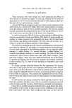
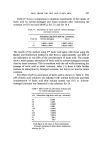
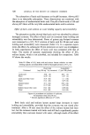
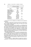
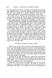
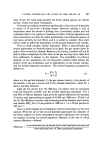
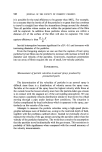
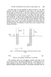
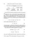
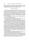
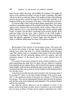
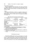
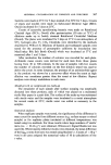
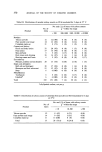
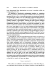
FACTORS CONTROLLING THE ACTION OF HAIR SPRAYS--Ill 549 The Pitot tube was first described by Henri de Pitot in 1732. Pitot measured velocities by immersing two open tubes to the same depth in flowing water, as shown in Fig. 1. The lower opening in one of the tubes was perpendicular to the flow and the rise in water in this tube was taken as an indication of the static pressure p• of the fluid. The other tube was bent through 90 ø so that its lower opening faced into the flow direction. The rise in water level in this tube was taken to be an indication of the total pressure Pt, i.e. the sum of the static and dynamic pressures, where the dynamic pressure «p0 V2 is the pressure equivalent of the kinetic energy of the flowing stream. The difference in water levels is thus a measure of the velocity of the fluid. Static p res su r•.•,•.•.• pressure I Total press••,• Flow Figure l. The Pitot-static tube method for measuring the velocity of a fluid stream. Thus Pt = P, + -}P0 V• (2) where P0 is the density of fluid and V its velocity. The instrument used in this investigation combines both tubes in one unit as shown in Fig. 2. The pressure differences (Pt- P•) produced are very small, especially at the lower velocities, and have to be measured on a specially designed inclined manometer. The particular instrument used was

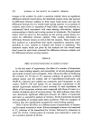
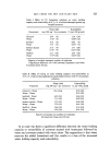
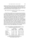
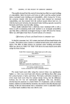
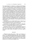
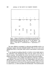
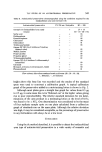
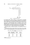
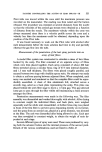
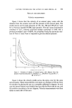
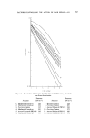
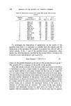
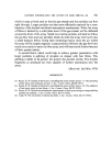
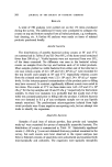
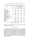
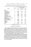
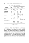
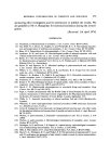
550 JOURNAL OF THE SOCIETY OF COSMETIC CHEMISTS Stohc pressure holes Flow •- f •,,•',• / Static Total pressure pressure Figure 2. A combined Pitot-static tube. the 'Portable airflow testing set Mark 4',* incorporating two adjustable limb manometers, each with several different inclinations. The manometer tubes were filled with a red dyed blend of paraffin having a specific gravity of 0.787 at 60øF. The static pressure tube was connected to the top of the manometer and the total pressure tube to the bottom so that only the differential pressure was measured. The scales of the manometer were cali- brated in inches of water and an alternative scale was also supplied so that air velocities in ft min -• could be read directly from the instrument. Pressurized packs were filled according to the specifications shown in Table I. The Pitot-static tube was placed within the aerosol spray cone at a given distance from the atomizing nozzle, and the aerosol button actuated. The Table I. Details of filling of aerosol cans for velocity measure- ments Pressure Resin-alcohol Propellant Freon 11/ (kN m -a) concentrate (•) (•o) Freon 12 152 40 60 45/15 221 40 60 35/25 290 40 60 24/36 359 40 60 14/46 * Airflow Developments Ltd.
Purchased for the exclusive use of nofirst nolast (unknown)
From: SCC Media Library & Resource Center (library.scconline.org)