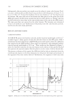
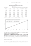
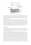
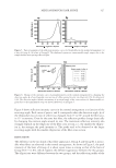
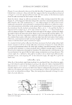
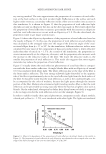
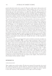
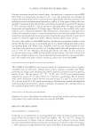
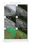
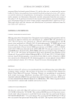
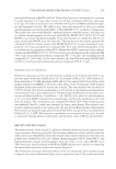
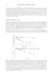
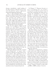
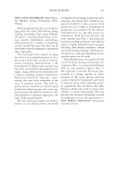
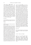
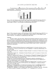
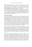
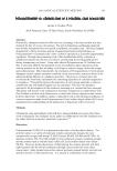
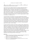
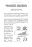
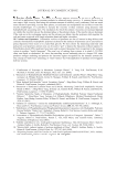
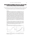
MECHANISM FOR HAIR SHINE 329 For further understanding of the front surface refl ection of a fi ber in the normal arrange- ment, refl ection from a dark hair fi ber was measured by goniophotometry. According to the fact that the specular refl ection phenomenon from a front surface of a fi ber is indepen- dent of the color of the fi ber, a goniophotometric curve of a dark fi ber can be a proper indication of the surface refl ection of a fi ber. Figure 9 shows the goniophotometric mea- surement result for a dark hair fi ber under the normal arrangement condition. The ellip- ticity of the fi ber was 0.75. Light penetrating into a dark fi ber is mostly absorbed by melanin granules, and the refl ection from the back surface of a fi ber is hardly able to be detected the refl ection observed in Figure 9 is, therefore, predominantly due to the sur- face refl ection. Actually the intensity-vs-receiving-angle curve of the dark hair (Figure 9) is well explained by the simulation results in Figure 8. As is calculated in Figure 8, the refl ection intensity curve yields no obvious peak and the refl ection intensity decreases monotonically from 0° to +90°. Such a strong refl ection as observed in the blonde hair Figure 8. Calculated intensity of front surface refl ection in the case of a cylinder (ellipticity: 1.0). Figure 9. Refl ection intensity of a dark hair fi ber in the normal arrangement (ellipticity: 0.75).

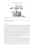
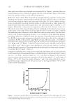
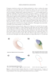
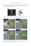
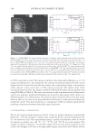
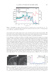
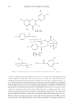
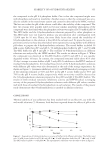
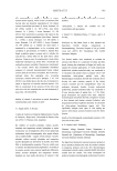
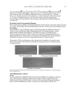
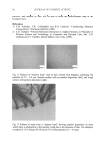
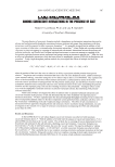
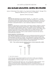
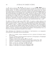
JOURNAL OF COSMETIC SCIENCE 330 (Figure 5) is not observed in the case of the dark hair fi ber. Comparison of the results with blonde hair in relation to those with dark hair suggests that the strong refl ection observed in Figure 5 is not the specular refl ection from the front surface of the fi ber but results from the refl ection from the back surface of the fi ber. From the drastic change in refl ection intensity by a fi ber rotating around the fi ber axis (Figure 6), it was suggested that this change was caused by a structural parameter of the fi ber related to the axial asymmetricity, i.e., the elliptical fi gure of a fi ber cross section. Light path simulations were performed to understand the behaviors of refl ection, refrac- tion, and transmission of the fi ber in the normal optical arrangement. It was assumed in the simulation that the medium surrounding a fi ber is air (n = 1.0), and that the fi ber is elliptical with an ellipticity, E, of 0.5 and a refractive index, n = 1.5. The simulation re- sults are shown in Figure 10, where the direction angle of the ellipse, φ (direction angle: the angle between the major axis of the ellipse cross section and the incident light) is 45°. Three types of rays were separatelty examined: refl ection light from the front surface of the cylinder (front surface refl ection), refl ection light from the back surface (back surface refl ection), and transmission light passing through both the front surface and the back surface of the fi ber (back surface transmission light). It is revealed in back surface refl ection that there are areas at the back surface where light doesn’t transmit at all but is totally refl ected (circled areas in Figure 10). Total refl ection is an optical phenomenon where all of the light striking a medium boundary (from a less optically dense medium to a denser medium with a shallow enough angle) is totally re- fl ected and no light passes through the boundary. The phenomenon is well known as the key mechanism of an optical fi ber for light energy transmission over long distances. The critical angle, θc, is defi ned as the angle of incidence above which total refl ection phe- nomenon occurs, and assigning 90° to the refraction angle, the angle θc is given by Snell’s law. sinθA/sinθB = nB/nA (1) where θA is the incident angle from medium A to medium B θB is the refraction angle nA is the refractive index of medium A and nB is the refractive index of medium B. For fi ber interior (n = 1.5) to air (n = 1.0) refl ection, total refl ection is expected to occur at an incident angle of 41.8° or above, by Snell’s law. Optical confi gurations giving rise to total refl ection are realized only when a cross-sectional fi gure of a fi ber is distorted from a per- fect circle, as is found for an ellipse. Thus, the strong shine observed in Group A is veri- fi ed to be total refl ection. Figure 10. Light path simulation with the direction angle, φ = 45°. The incident light is irradiated from the left side of the fi gure.
Purchased for the exclusive use of nofirst nolast (unknown)
From: SCC Media Library & Resource Center (library.scconline.org)