RHEOLOGICAL STUDIES OF NEW CREAM BASES 225 ments would therefore include measurements at the following speeds (con- cerning times, etc., see under the respective points 2 - 7), for RVT: 0.5 - 10 - 20 - 50 - 100 - 100 - 100 - 50 - 20 - 10 - 5 - 2.5 - 1 - 0.5 rpm. Stages 4-5. After 60 sec, the pointer is locked at the particular deflec- tion by depressing the clutch and the speed is immediately altered to the next value in the programme. The operator will then have time to record the scale reading. The clutch must be depressed for the whole time since the spindle would now be rotating at the next speed. After taking the reading, the clutch is released and the pointer will thereafter change to the new value corresponding to that speed. At the highest speeds [50 and 100 rpm (RVT)], it is not possible to take a reading while the spindle is rotating. Rotation of the spindle must therefore be stopped for a few seconds. No time correction is, however, necessary since a few seconds' difference in the rotation time is negligible after 60 sec. The reason for the comparativelylongtime of 60 sec before each reading is taken is due to the fact that the registration of the deflection is not automatic. A few seconds' difference in the time will be of negligible importance, whilst the same error at a rotation time of 15 or 30 sec would result in a considerable uncertainty in the measurement of the up-curve where the break-down of the structure during the first 15-30 sec can be quite rapid. Stage 6. The readings at the highest rotation speeds are repeated in order that non-uniform flow can be more easily detected. Stages 7-8. The measurements on the down-curve can be taken at shorter intervals since the values obtained, in contrast to those for the up-curve, are only slightly dependent on the time and thus the reason for the long rotation time is not valid here. It is only necessary to wait until the deflection has become stabilized. Interpretation of the results A. A correction must be made for the shaft of the spindle since the equations given above for the T-shaped spindles are valid only if this has been done. In theory this correction can be obtained by carrying out a complete measurement using only the shaft of the spindle. This, however, means a considerable increase in the amount of work and such measurements with the shaft alone - according to Frykl/Sf's experi- ence - often give unreliable results in plastic systems. The same

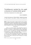
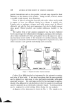
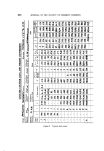
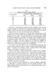
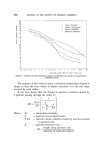
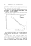
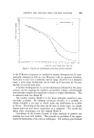
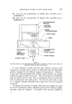
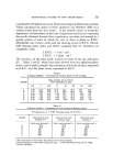
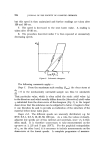
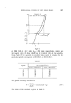
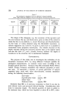
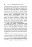
226 JOURNAL OF THE SOCIETY OF COSMETIC CHEMISTS accuracy can be obtained by applying a general, empirically-found correc- tion for all plastic systems, the magnitude of which for different spindles can be found in Table III. This procedure is, of course, incorrect from a theoretical point of view since the correction is in reality dependent on the rheological properties of the substance under investigation. Even for strongly thixotropic systems, it has nevertheless been shown that the result obtained in this way differs at most by 5% from the value found when the correction is made using measurements with the spindle shaft alone. Table III Correction for the spindle shaft. T-shaped spindles. Spindle C ---- S -- correction ß S correction z 0.00 0.01 0.02 0.04 0.08 0.20 Cmax = Smax- correction. Smax correction 0.00 0.00 0.01 0.01 0.02 0.05 •Does not apply to correction of Smax. B. A rheogram is constructed by plotting, on mm graph paper (Fig. 3), the scale reading on the ordinate and the corresponding rotation speed (rpm) on the abscissa. The up-curve is constructed using the values obtained when increasing the rotation speed, and the down-curve similarly when decreasing the speed. The values from 5 rpm to 0.5 rpm on the down-curve are, however, plotted on an auxiliary diagram with a larger scale, in which rpm is used as abscissa, in order to make possible a linear extrapolation of **. From the diagram thus obtained, it is possible to calculate *s, ** and U for the reference point mentioned in page 220. % and ,• are obtained from the values derived from the diagram for Stoa • and S O by multiplying by a certain factor which has been given in Table II for each spindle and which has been calculated from (XIV), after correcting for the influence of the spindle shaft. Since the viscosity usually varies with the rate of shear, the calculation of this property must be made at the same rate of shear, independent of the spindle used for the measurement, if com- parable results are to be obtained. For most purposes it is best to calculate the viscosity at 98 B.R.U. (RV, HA and HB with flma • = 100 rpm)
Purchased for the exclusive use of nofirst nolast (unknown)
From: SCC Media Library & Resource Center (library.scconline.org)