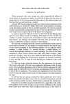
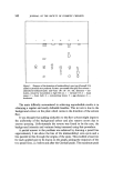
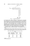
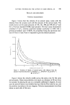
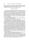
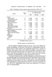
550 JOURNAL OF THE SOCIETY OF COSMETIC CHEMISTS Stohc pressure holes Flow •- f •,,•',• / Static Total pressure pressure Figure 2. A combined Pitot-static tube. the 'Portable airflow testing set Mark 4',* incorporating two adjustable limb manometers, each with several different inclinations. The manometer tubes were filled with a red dyed blend of paraffin having a specific gravity of 0.787 at 60øF. The static pressure tube was connected to the top of the manometer and the total pressure tube to the bottom so that only the differential pressure was measured. The scales of the manometer were cali- brated in inches of water and an alternative scale was also supplied so that air velocities in ft min -• could be read directly from the instrument. Pressurized packs were filled according to the specifications shown in Table I. The Pitot-static tube was placed within the aerosol spray cone at a given distance from the atomizing nozzle, and the aerosol button actuated. The Table I. Details of filling of aerosol cans for velocity measure- ments Pressure Resin-alcohol Propellant Freon 11/ (kN m -a) concentrate (•) (•o) Freon 12 152 40 60 45/15 221 40 60 35/25 290 40 60 24/36 359 40 60 14/46 * Airflow Developments Ltd.

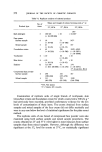
FACTORS CONTROLLING THE ACTION OF HAIR SPRAYS--III 551 Pitot tube was moved within the cone until the maximum pressure was recorded on the manometer. The reading was then noted and the button released. The procedure was repeated at several distances from the nozzle so that the velocities of the aerosol gas stream were obtained as a function of distance from the nozzle. The maximum velocity within the cone was always measured since there is a velocity profile across the cone and a velocity less than the maximum could be obtained, depending upon the position of the Pitot tube. It was found necessary to wash out the Pitot tube with alcohol after each measurement before the resin solution had time to dry and partially obstruct the gas flow into the tube. Measurement of the penetration of the hair spray particles into an array of hair fibres A model filter system was constructed to simulate a mass of hair fibres backed by the scalp. The filter consisted of six separate arrays of fibres which were then placed together. Each array consisted of about 200 hair fibres stretched across a circular brass ring of 47.5 mm internal diameter, and 1.5 mm wall thickness. The fibres were placed roughly parallel, and secured between two rings with Araldite epoxy resin. No attempt was made to obtain a uniform spacing between adjacent fibres. When completed, each array was marked and numbered so that the complete filter could be repro- ducibly assembled. A sheet of thin aluminium foil, attached across a seventh ring, acted as a back plate representing the scalp. This plate was placed behind the sixth filter stage to leave a 1.5 mm gap. This gap allowed some gas to pass through the filter whilst still maintaining a back pressure amongst the fibres. Penetration measurements were made in the following way. The filter assembly was dismantled and washed thoroughly with alcohol. After drying to constant weight the individual filters, and back plate, were weighed separately and the whole unit reassembled. A further brass ring was placed in front of the first filter to prevent spray depositing directly on its former, and the spray from an aerosol can, placed at a given distance, was directed at the filter. The unit was dismantled after being allowed to dry. Each part was then reweighed to constant weight, to obtain the weight of resin de- posited at each stage. Several different types of spray were used. These were produced by vary- ing both the actuator button and the internal pressure of the aerosol pack. Details of the various combinations used are listed in Table II.
Purchased for the exclusive use of nofirst nolast (unknown)
From: SCC Media Library & Resource Center (library.scconline.org)