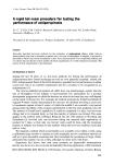
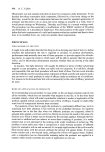
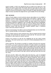
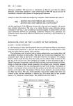
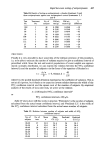
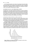
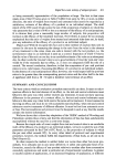
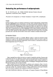
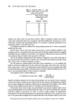
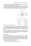
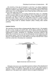
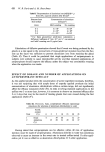
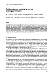
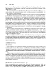
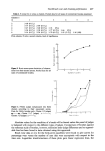
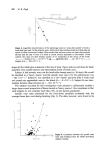
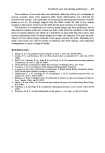
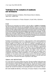
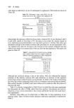
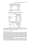
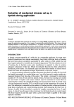
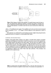
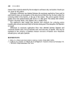
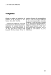
Mechanical stresses in lipstick 443 Figure 2. Block diagram of lipstick stress equipment. The applied stresses caused the beam to bend. The resulting strains affected the resistance of opposing strain gauges. The gauges were part of a Wheatstone resistance bridge whose output was then amplified. The two signals were either recorded separately, or combined to give the vector sum (or resolved) force before being recorded. with a -t- 5 V stabilised power supply. The amplifiers and vector sum device were energised from a stabilised -t- 15, 0, - 15 V supply. A block diagram of the equipment is given in Fig. 2. The apparatus was calibrated for pure bending loads by weights being hung from the application point of a lipstick in a horizontally held holder. LIPSTICK APPLICATION TRIAL Initially twenty-eight female subjects were asked to describe their method of lipstick application and frequency of use (which varied from non-users, to an hourly application). Each subject selected one lipstick from each range. The first stick was impaled on the strain-gauged beam and the subject was asked to apply the lipstick in front of a mirror in their normal manner. The applied lipstick was removed from the lips with a tissue. This was repeated for a total of six applications. The first stick was removed and replaced by the second stick chosen by the subject from the second range. After repeating the above six applications subjects were asked which stick they preferred. This procedure was repeated on five separate days. • 0'( ,,o 0.4 J'O -- I o I 2 3 4 5 6 7 8 Time (sec) Figure 3. A typical vector sum lipstick application force v. time trace. This trace spans 7 sec during which the lipstick was applied in several strokes. The maximum force approached 1 N.

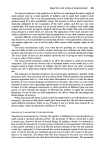
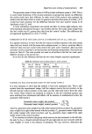
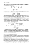
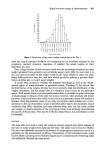
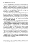
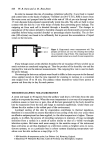
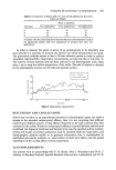
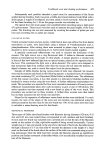
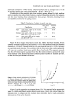
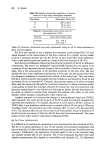
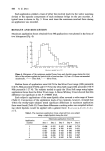
444 R. G. Drew Each application yielded a trace of either the resolved load (via the vector summing device) or the separate components of each resistance bridge on the pen recorder. A typical trace is shown in Fig. 3. From each trace the maximum resolved force during an application was recorded. RESULTS AND DISCUSSION Maximum application forces obtained from 840 applications were plotted in the form of two histograms (Fig. 4). 120 - •,, Ioo .s 80 o • e0 • 40 z 20 0'2 0'4 0'6 0'8 I-0 1'2 1.4 1.6 1.8 2.0 2'2 Maximum applied force (N) l*igt•e 4. Histogram of the maximum applied forces from each lipstick range during the trial. Most of the subjects applied the lipsticks with a force less than 1 N, but a 2 N force was exceeded occasionally. -- Ultra Soft .... Silver Frost. Median forces of application were 0-68 N for the Silver Frost range (10th percentile 0.46 N, 90th percentile 0.92N) and 0.73 N for the Ultra Soft range (10th percentile 0.50 N 90th percentile 1'27 N). The subjects tended to apply the Ultra Soft range using higher application forces than the Silver Frost range. A Mann-Whitney U-test showed that this difference was significant at the P 0.00001 level. Each subject's applications of the same lipstick often covered a wide range of forces (Table I). Comparison of the application loads of two lipsticks, however, revealed that within the twenty-eight subjects tested significant differences in maximum application force were found (Table II). From these differences a ranking order was compiled indicat- ing which lipsticks would be applied with a greater force: b c a y, e w v x zd. Table I. The maximum application forces observed from one subject using a single lipstick during the trial 1 0.604 0.512 0.443 0.660 0.738 2 0.667 0.438 0.708 0.676 0.851 3 0.811 0-678 0.743 0.640 0.808 4 0.397 0.604 0.682 0.996 0.705 5 0.261 0.696 0.732 0.931 0.847 6 0.642 0.774 0.942 0.782 0.829 Maximum application force (N) Application number Day 1 Day 2 Day 3 Day 4 Day 5
Purchased for the exclusive use of nofirst nolast (unknown)
From: SCC Media Library & Resource Center (library.scconline.org)