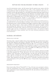
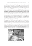
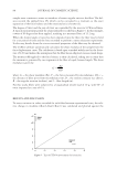
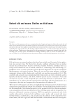
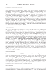
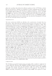
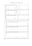
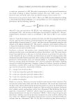
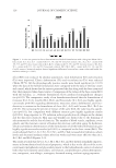
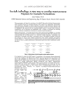
NEW METHOD FOR MEASUREMENT OF FIBER TORSION 85 (mass 6.5 g) was attached to the lower end of the fi ber. The pendulum bob is composed of a groove for the fi ber crimp and a disk containing a number of equally sized and spaced slits through which light can pass. When the crimped fi ber is attached to the torsion rig and the pendulum bob, the plane in which the bob oscillates should be normal to the direction of the fi ber. When mounted on the torsion rig, the pendulum bob is orientated between a light source and sensor. Although care is taken in the preparation of fi bers of 30-mm gauge length, some fi bers may be slightly longer or shorter, and the rig is fi tted with an adjustment screw to make small adjustments to the position of the bob between the light source and sensor. When a measurement is to be made, the custom rig-operating software is initiated and experimental parameters entered. An initial oscillation of 135° at a rate of 75°/s, with a 30-s data acquisition time and a 50-Hz sampling rate, is employed. Following entry of the experimental parameters, the motor on the top of the rig is initi- ated and rotates to set the oscillation of the fi ber and bob in motion. The frequency and amplitude and the dissipation in rotation of the fi ber and bob are determined by record- ing the intermittent signal of the light incident on the sensor as the slits and fi lled sec- tions of the bob pass by the light source. The data is collected electronically and can be displayed as shown in Figure 2. The shear modulus was calculated using the method described below (28). The frequency of a torsional pendulum is given by: 1 2S C f I where f = the frequency in Hz, C = torsional rigidity, and I = the moment of inertia of the pendulum bob in kg/m2. Figure 2. Typical response produced by a fi ber in free oscillation on torsion rig following application of excitation force.

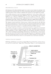
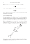
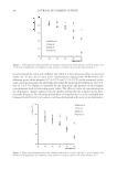
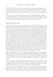
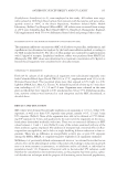
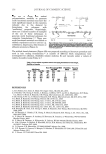
JOURNAL OF COSMETIC SCIENCE 86 For fi bers with non-circular cross sections, the shear modulus is calculated by: CL G D where G = the shear modulus in Pa and D = the torsion constant in m4. The torsion con- stant is calculated as follows: S 3 2 a b3 D a b2 where a and b are semi-major and semi-minor axes of the ellipse (in meters), determined using the FDAS as described above. AUTOMATED FIBER TORSION TESTER In conjunction with Unilever Research & Development, Port Sunlight, Dia-Stron Ltd. has developed the FTT950 automated fi ber torsion test. This instrument has the dual advantages of automated operation, signifi cantly reducing manual operating time, and direct shear force measurement when compared with indirect methods such as the rota- tional pendulum. The dimensional properties of samples are determined as described above and then fur- ther determined with the addition of a third plastic fi xing, a torsion clip, that is attached to the central section of the 30-mm sample length, as shown in Figure 3. The torsion clip is 14-mm long, leaving two 8-mm test length sections. The torsion clip has two vanes Figure 3. Direct torsion measurement—principle of operation. The two end tabs are shown rotated through an angle Θ with respect to the central torsion tab. The vane on the torsion tab applies a force F at moment arm length L onto the stainless steel pin of the force balance.
Purchased for the exclusive use of nofirst nolast (unknown)
From: SCC Media Library & Resource Center (library.scconline.org)