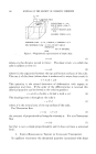
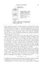
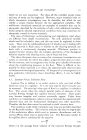
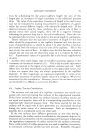
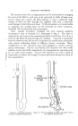
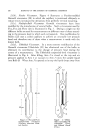
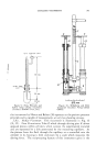
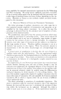
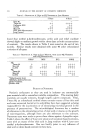
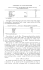
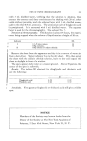
CAPILLARY VISCOMETRY 359 The variation from this average pressure can be minimized by arranging for most of the fluid in each arm to be contained in bulbs of large cross section which also contain the fluid surfaces so that a relatively large volume of fluid can flow through the capillary with only a relatively small change in the hydrostatic head. If this procedure is not practicable or adequate, the average head can be corrected for these variations. Swindells (12) has discussed these corrections. 5.1(a). Ostwald l/iscometer. Probably the most classical capillary viscometer is that of Ostwald (17), illustrated in Fig. 3. The time is observed for the level of the experimental fluid to fall from ,4 to B as a _• result of the fiuid's flowing through the capillary. Viscosity is calculated from the observed data by the use of equation 19, usually after calibration 2 with several calibrating fluids of different known viscosities. Many modifications of this viscometer have been designed to achieve various . special advantages. Cannon and Fenske (18) describe two with small " capillary radius and bulbs, respectively, for measuring low viscosities and for use with small samples. Cannon (19) describes one with a bulb of large radius to reduce the change in hydrostatic head during the course of the measurement. A _ _ Figure 3.--Ostwald viscometer (Courtesy) Edward Atrnold & Co.). •Mss bt'iclge • oetcheline . 28 to $Omro. $ Figure 4.--Fenske-modified Ostwald viscometer (Cour- tesy Edward •lrnold & Co.).

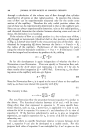
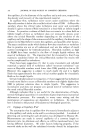
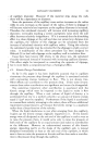
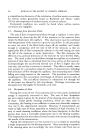
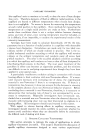
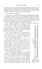
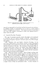
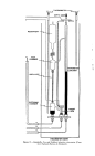
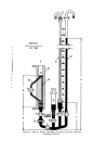
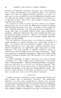
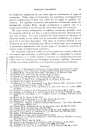
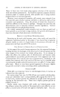
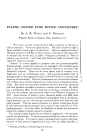
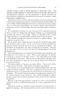
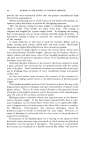
360 JOURNAL OF THE SOCIETY OF COSMETIC CHEMISTS 5.1(b). Fenske lZiscometer. Figure 4 illustrates a Fenske-modified Ostwald viscometer (20) in which the capillary is positioned obliquely to reduce errors introduced by deviations from perfectly vertical mounting. 5.1(c). Multiple-Bulb lZiscometer. Ostwald viscometers have been modified by the introduction of several bulbs. Such a viscometer used by Fox, Fox and Flory (21) is illustrated in Fig. $. During a single run the different bulbs are used for measurements at different rates of shear accord- ing to the pressure head to which each corresponds. One modification by Stabin (22) uses a coiled capillary to achieve an unusually low pressure head and therefore rate of shear when a measurement is made with the lowest bulb. 5.1(d). Ubbe/ohde lZiscometer. In a more extreme modification of the Ostwald viscometer Ubbelohde (23) has eliminated one of the bulbs to eliminate its contribution to the change of pressure head during the course of a measurement. The Ubbelohde suspended-level viscometer is illustrated in Fig. 6. After filling, Arm 3 is closed at the top and air pressure applied to Arm 1 or vacuum to Arm 2 raises the sample liquid into Bulb B. When Arm 3 is opened at its top the liquid drops away from 3O * ]O 02 / 2 3 20'era. 60 cm. 20'cm. , Figure 5.--Fox and Flory Figure 6.--Ubbel- multiple-bulb viscometer ohde suspended level (Courtesy /lmerican Chem- viscometer (Cour- ical Society). tesy Edward /lrnold • Co.).
Purchased for the exclusive use of nofirst nolast (unknown)
From: SCC Media Library & Resource Center (library.scconline.org)