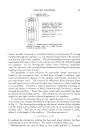
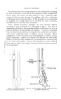
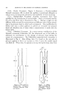
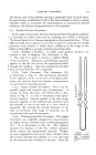
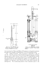
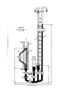
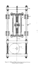
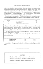
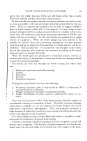
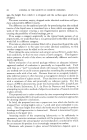
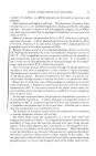
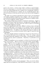
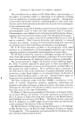
CAPILLARY VISCOMETRY 363 12/5 Spherical Joint 190 mm. 19/38 Taper daint ZSjmm. Figure 9.--Stow, Horowitz and Elliott rising column viscometer (Courtesy •lcademic Press, In.). F F f , I , I t I [ I , I 100 mm Figure 10.--Willenberg and Fritz viscometer (Courtesy I/erlag Chemie GmbH). this instrument by Maron and Belner (30) operates on the positive pressure principle and is capable of measurements at very low shearing stresses. 5.3(c). McKee l•iscometer. This viscometer is illustrated in Fig. 13 (31, 32). Cam H motivates Yoke E which through driving pins K drives opposed pistons within cylinders •hich contain tke experimental material and are separated by a disk penetrated by the measuring capillary. As the pistons force the fluid through the capillary at a controlled rate the cylinder in its housing is held stationary by a scale which measures the driving force. The reciprocating feature of this instrument gives it the

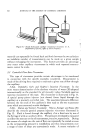
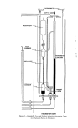
THERMOMETER---..-•.,• DEPTH GAGE RESERVOIR EXIT CHAMBER CAPILLARY MANOMETER LONG ARM ENTRANCE CHAMBER SHORT ARM VISC OMETER BATH Figure 11.--Swindells, Coe and Godfrey injection viscometer (Cour- tesy National Bureau of Standards).
Purchased for the exclusive use of nofirst nolast (unknown)
From: SCC Media Library & Resource Center (library.scconline.org)