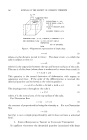
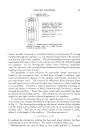
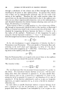
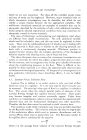
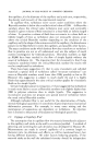
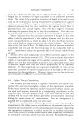
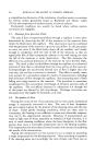
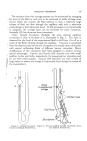
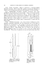
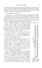
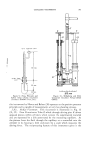
CAPILLARY VISCOMETRY 361 the bottom end of the capillary leaving a suspended level of liquid there. In some further modifications bulb .4 has been enlarged to form a mixing chamber which is convenient for measurements on successively diluted i solutions the dilution being performed in this chamber. 5.2. Positive Pressure l/iscometers In this type of viscometer the force driving the fluid through the capillary is controlled at a fixed value and the resulting rate of flow is measured. The force of gravity is of course superposed on the controlled force. If the effective head due to gravity is not zero it must be corrected for in high precision work, whether it results from a difference in the shape of two bulbs or from different average vertical levels of the bulbs. $.2(a). Bingham l/iscometer. A widely used positive pressure vis- cometer is that of Bingham (24), illustrated in Fig. 7. The trap `4 is used to ensure a uniform filling of the viscometer. Measured, controlled gas pressure applied to the left arm forces the experimental fluid through the capillary. The time required for the fluid level to move from B to D is measured. $.2(b). Tsuda lriscometer. This viscometer (25) is illustrated in Fig. 8. The horizontal placement of the capillary, shown at the left of the figure, elim- inates any gravity head and permits measurements at extremely low shearing stresses. 5.2(c). Rising Column Ifiscometer. This is an ex- tremely simple and versatile type of viscometeAillus-experi-isthe(26)in version by Stow, Horowitz and Elliott trated in Fig. 9. A tube is immersed mental material. Vacuum applied to the tube or gas B pressure applied to the experimental material forces the material to rise in the tube at a rate which is measured. By varying the internal diameter of the tube an extremely wide range of viscosities can be covered with this type of instrument. 5.2(d). 14/illenberg and Fritz lZiscometer. This rugged viscometer was originally designed for measurements on highly viscous materials such as lubricating greases (27). It is illustrated in Fig. 10. The capillary connects the bottoms of the two vertical cylinders which contain the experimental material. Weights on pans supported by pistons in these cylinders force the material through the capillary at a rate indicated by the measured rate of descent of the pan. Since the Figure 7.- Bingham viscom- eter (courtesy Edward •trnoM & Co.).

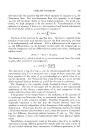
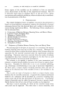
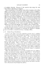
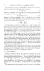
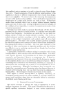
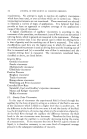
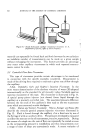
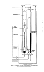
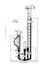
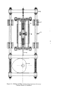
362 JOURNAL OF THE SOCIETY OF COSMETIC CHEMISTS Figure 8.--Tsuda horizontal capillary viscometer (Courtesy U.S. Department of )•ustice, 02rice of Allien Property). material can repeatedly be forced back and forth between the two cylinders an indefinite number of measurements can be made on a given sample without recharging the instrument. This feature provides an advantage over many other capillary viscometers in which such repeated measure- ments cannot be made. 5.3 Controlled Flow Rate lZiscometers This type of viscometer provides certain advantages to be mentioned in connection with the specific examples considered. Measurement is made of the driving force required to maintain a given rate of flow through the capillary. 5.3(a). Swindells', Coe's and Godfrey's Injection lZiscometer. In the most recent determination of the absolute viscosity of water (28) adopted internationally as the standard for all viscosity values Swindells used an injection viscometer of this type. His viscometer is illustrated in Fig. 11. A special pump piston injector (not shown) forces liquid through the capillary at a precisely controlled rate. The associated pressure difference between the two ends of the capillary is then read on the two manometer arms which are connected outside the figure. 5.3(b). Maron and Kreiger IGscometer. Maron, Kreiger and Sisko (29) describe the versatile general purpose injection viscometer illustrated in Fig. 12. Fluid is forced through the capillary d at a fixed rate by use of' the Syringe G with an auxiliary drive. The pressure developed is measured on either the mercury or the oil manometers, w and m, respectively. During the course of a single run the rate of flow can repeatedly be varied as soon as the corresponding pressure is established, and thus measurements over a range of rates of shear are conveniently made. A recent variation of
Purchased for the exclusive use of nofirst nolast (unknown)
From: SCC Media Library & Resource Center (library.scconline.org)