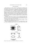
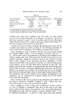
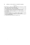
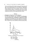
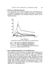
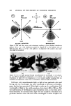
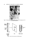
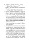
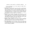
412 JOURNAL OF THE SOCIETY OF COSMETIC CHEMISTS optical anisotropism, is a result of electron orbit polarizability and/or a re- fraetive index differential between a crystal and its surrounding medium in which the crystal is embedded (2, 3, 4). The quantitative measure of bire- fringence, referred to as the numerical birefringence, is an extremely sensitive measure of optical anisotropism, wh'ch arises from molecular orientation 5). The cortical region of a human hair is optically anisotropic (3, 6). In its function as the maior fiber component (7), the cortex contributes 92 per cent to the elasticity of the hair. This is borne out by an analysis of the correlation matrix of a multiple linear regression model that explains the factors con- tributing to elasticity in hair (8, 14). In the course of a cosmetic treatment, be it chemical or mechanical in nature, the condition of a hair fiber is changed. The parameter of elasticity, or the resistance to and recovery from deformation by force, plays a maior role in the final fiber condition after treatment(1). The change of condition during cosmetic treatment is due to molecular bonding changes, which occur mainly in the cortex (7, 9). Therefore, the action of cosmetics, which affect condition and elasticity, should also affect the optical anisotropism of the cortex. Thus numerical bire- fringence, as a very sens:tive measure of molecular orientation, emerges as having the potential to very accurately determine hair condition. This paper presents a quantitative system of analysis of human hair condi- tion, based upon the optical phenomenon of numerical birefringence. Theory of Bitefringe Plane polarized light is utilized to observe the phenomenon of birefrin- gence. Ordinary light vibrates in waves, traveling in random planes perpen- dicular to the direction of propagation. By placing a polarization plate in front of a light soume, only those waves tarveling in planes parallel to the axis of polarization of the plate are transmitted the others being absorbed (Fig. 1A). An anisotropic material has two unique optical properties as follows: (1) any one plane of light waves striking an anisotropic material is split into two wave-planes, traveling 90 ø relative to each other and 45 ø each relative to the original plane of propagation (Fig. i B). Hence the term double refraction or birefringence (2) a plane of light passing through an anisotropic material encounters a path of a different refractive index, and thus travels at a different veloc'ty, in each different direction of traverse (2, 5). Therefore, a wave of plane polarized light strikes an anisotropic material, is split into two waves, one of which, the ordinary or simply fast wave, is travel- ing through a path of lesser refractive index, and thus faster than the extra- ordinary or slow wave, which is traveling at a perpendicular angle in a more difficult path of higher refractive index (2, 5).

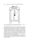
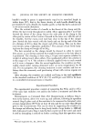
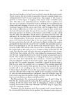
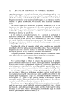
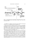
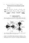
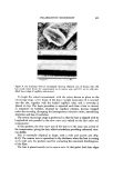
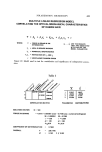
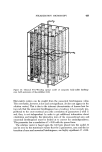
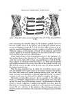
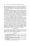
POLARIZATION MICROSCOPY 413 ORDINARY LIGHT AND PLANE POLARIZED LIGHT AXIS OF POLARIZATION ORDINARY LIGHT ' POLARIZER PLANE POLARIZED LIGHT DIRECTION Of PROPAGATION PLANE POLARIZED LIGHT PASSING THROUGH AN ANISOTROPIC MEDIUM FAST WAVE ANISOTROPIC WAVE MEDIUM 2 WAVE PLANES 90 ø TO EACH OTHER 45 ø EACH TO THE PLANE POLARIZED LIGHT Figure 1. (A) Ordinary light waves being polarized and (B) ordinary light waves further split into two perpendicular waves, each traveling at different velocity, while travers- ing anisotropic medium The difference in refractive index between the two paths of the fast and slow wave (n,o-nl) equals the numerical birefringence (2). As the 2 waves advance through the material, the slow wave increasingly lags behind the fast wave in direct proportion to the numerical birefringence (the difference in path velocities) and to the distance or thickness traveled. This quantity of "lag," measured in units of distance, is termed retardation. Hence the formulation, retardation equals numer_'cal birefringence x thick- ness or A= (n2-nl)d. The numerical birefringence is determined by measuring the retardation and the thickness (2). The retardation lag of the slow relative to the fast wave causes the two waves to go out of phase with each other (Fig. 2). These two waves, exiting the anisotropic material, interfere with each other, causing an elliptical interference pattern. In Fig. 3(A) the two waves are coming at you in phase with each other, the retardation distance having been some full multiple of the wavelength (A = nX). They are vibrating in unison, i.e., each reaching points 1-20 at the same time from points A, A' to B, B'. The elliptical inter- ference pattern is centered around an axis, formed by connecting the points of intersection of consecutive lines, drawn from the wave position at a particular instant, perpendicular to the wave axis. In Fig. 3 (B), the slow wave has been
Purchased for the exclusive use of nofirst nolast (unknown)
From: SCC Media Library & Resource Center (library.scconline.org)