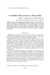
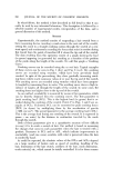
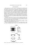
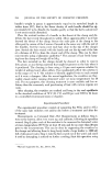
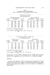
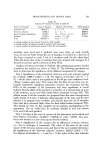
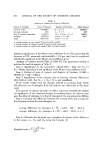
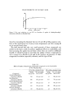
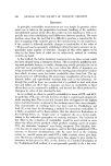
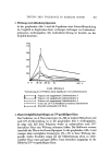
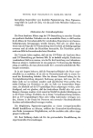
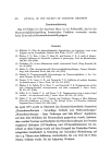
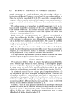
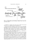
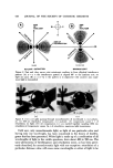
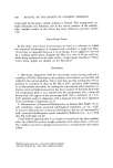
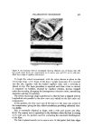
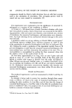
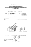
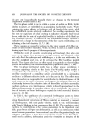
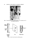
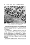
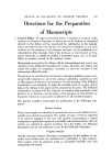
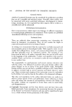
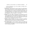
414 JOURNAL OF THE SOCIETY OF COSMETIC CHEMISTS INCREASING RETARDATION OF THE SLOW RELATIVE TO FAST WAVE WAVE s,ow/w-,, WAVE / •,,_//•, _'g,X RETARDED (IN PHASE) \_/ k../ / 1/4 ),RETARDED 1/,, X RETARDED 1 ),RETARDED ('IN PHASE] DIRECTION OF RETARDATION •' DIRECTION OF TRAVEL Figure 2. Two parallel waves of equal length X, traveling different velocities. As slow wave increasingly retards from fast wave, two go in and out of phase with each other • ELLIPTICAL /I" RESULTANT /•""• INTERFERENCE / ELLIPTICAL •, /•AXIS • 1 INTERFERENCE • / PATTERN • /(NEGATIVE IMAGE) • • /•• ., ( • • t •J •" • AXIS OF POLARIZATION '••'• I •• • ..•/_•• • •{gure 3. Ode•t•tJo• o• e]]•tJe•] J•te•e•egee •tte• •o•me• by two J•te•ed•g w•ves (A) • p•ase a• (•) ¾2 X o.t o• p•se (see tezt) retarded some full multiple of the wavelength plus one-half (A = n + 1/2X). In this case, as the fast wave advances from point A, through points 1-20, finally to point B, the slow wave, being 1/2X out of phase, advances from point

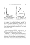
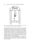
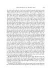
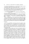
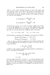
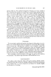
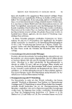
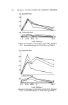
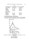
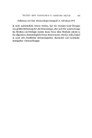
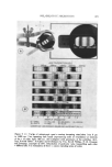
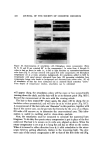
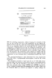
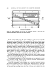
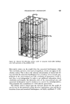
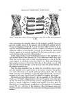
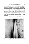
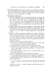
POLARIZATION MICROSCOPY 415 Figure 4. (A) Axis of polarization (B) slow wave axes of compensator and hair (C) fast wave axes of compensator and hair. In wave axes of hair and background retardation compensator: parallel alignment produces summation of their retardations-perpendicular alignment produces subtraction of their ret. ardations B', through points 20-1, finally to point A' the elliptical interference pattern has shifted 90 ø (2). An important concept, utilized in the measurement of numerical birefrin- gence, is that of addition and subtraction of retardation. If anisotropic objects are placed in line (i.e., one on top of another) in the path of light of a polari- zation system with their slow wave axes parallel, the total amount of retarda- tion in the system equals the stLm of the retardation of the individual Objects. If, however, the slow wave axes are aligned perpendicular to each other, the total retardation is equal to the difference between the objects as they tend to cancel each other out (Fig. 4) (2). The anisotropic material being illuminated as has been described (Fig. i(B)) is viewed through a second polarizing plate, termed the analyzer, whose axis of polarization is 90 ø to that of the "bottom" polarizer. Only when a portion of the elliptical interference pattern lies in the same axis as that of the analyzer, does light pass thus, light due to retardation, which in turn is caused by the product of numerical birefringence and thickness, can be seen and measured. No light is passed, a condition referred t.o as extinction, when A = n)t maximtun light is passed when A = n + ¾2)t (Figs. 5 and 6) (2, 5).
Purchased for the exclusive use of nofirst nolast (unknown)
From: SCC Media Library & Resource Center (library.scconline.org)