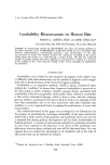
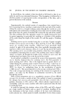
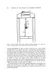
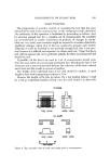
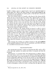
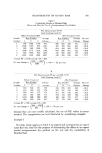
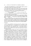
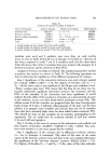
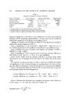
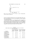
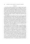
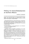
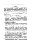
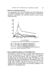
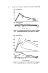
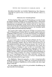
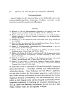
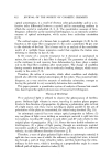
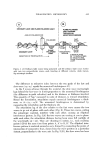
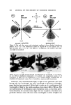
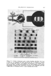
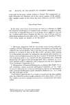
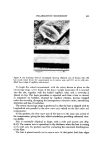
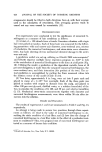
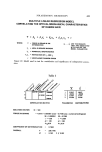
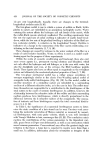
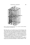
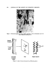
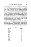
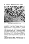
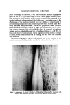
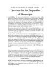
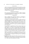
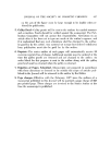
416 JOURNAL OF THE SOCIETY OF COSMETIC CHEMISTS N OF W E OF ANALYZER ANALYZER S A--n•, NO LIGHT-- EXTINCTION AXIS OF POLARIZATION A=n+l/2•, MAXIMUM LIGHT Figure 5. Fast and slow waves exist anisotropic medium to form elliptical interference pattern: (A) /x = n X: the interference pattern is aligned 90 ø to the analyzer axis no light can pass (B) _X = n q-% X: the pattern is in alignment with analyzer axis maxi- mum light is transmitted (. ....i• :.:. .... ,. .• ' : •"- .... S•..•. • . . ??3 : ß • •: .. :. •-•. :...=: .• ... • ß .:.,. :: -.: . ::. .. .. . •' . .... .C•...?d:• • % •. :.: •-..-- . •--.:.•:. . : .... C e (*) (•) Figure 6. (A) (•) Light passing through monoc•ometer of wavelength X (•) polariz- er (c) 546 nm retardation compensator (•) analyzer. (A) compensator causes 1 X of retardation no light (B) [2 compensators (c) are stacked together equaling 1092 nm retardation]. Com•ensator causes 1% x of retardation m,•imu]n light •ansmissivn Until now, only monochromatic light, or light of one particular color and having only one wavelength, has been considered in the theory of birefrin- gence that has been presented. White light is made up of a combination of all wavelengths of light in the visible spectrum, from about 400 to 700 nm. The same phenomena of birefringence and retardation occur, as has been previ- ously described, for monochromatic light with one exception: retardation of a particular distance value will cause some wavelengths or colors of light to be

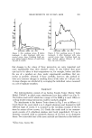
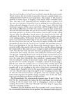
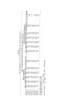
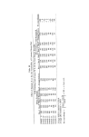
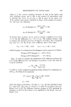
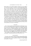
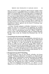
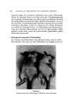
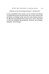
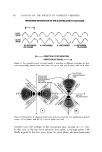
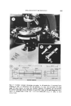
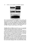
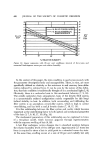
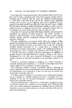
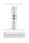
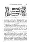
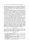
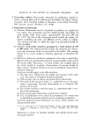
POLABIZATION MICBOSCOPY 417 Figure 7. (A) Wedge of aniosotropic quartz causing increasing retardation from 0 •an to'1.650 t•m, Note repeating clark bands (representing order of retardation) at intervals of the x of white light: 550 nm. (B) [Adapted with permission of the publisher (2)], from Mineral Optics: Principles and Techniques by Win. Revell Phillips, W. H. Freeman and Company, copyright ¸ 1971. Retardation of particular value transmitting each color X differentially. The summation of these Xs causes repeating series of colors
Purchased for the exclusive use of nofirst nolast (unknown)
From: SCC Media Library & Resource Center (library.scconline.org)