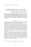
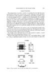
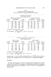
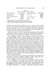
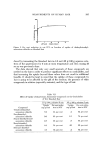
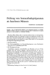
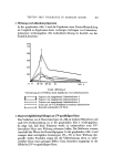
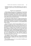
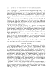
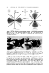
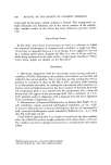
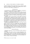
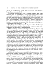
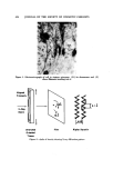
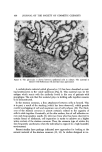
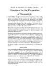
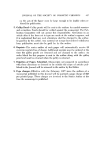
4-22 JOURNAL OF THE SOCIETY OF COSMETIC CHEMISTS :•':" ":'¾" ' ß -. i ::•--!•"!..: ..::".'.. •'""7•.'" . ....... ?..'•.. .... Figure 10. Determination of ret•dation with E•in•aus rotary compensator. (H•rs B, C, D, and E are oriented 90 ø to the compensator. ) In series from A •rough E, colors in hair go down in order i.e., in leR to right direction on summation-interference color chart (Fig. 7). (A) hair oriented with quar• first order compensator (B) Ehringhaus compensator set at • (note extinction background) (C) retardation added to field by compensator with equM amount subtracted from hair (D) increasing retardation from compensator brings color bands to background and decreased hair center color (E) •1 of retardation of hair has been subtracted out in centered black extinction "arro•v." From degree of compensator rotation, retardation can be c•culated will appear sharp, the retardation colors •vill be more or less symmetrically running down the shaft, and the hair will be at its thinnest point (Fig. 9(B) ). Record the measurement of the axis with the viewing reticle. The hair is then rotated 90 ø where again, .the edges will be sharp, the re- tardation colors symmetrical, and will now be at its widest point ( Fig. 9(C)). A measurement of the hair wide axis "diameter" in this position, together with that of the narrow axis, can be put into the formula for the area of an ellipse, 0.5 wide x 0.5 narrow x rr, to determine the cross-sectional area. This infor- mation is useful in swelling and/or stress-strain analysis. Next, the retardation must be measured to calculate the numerical bire- fringence. To do this, the quartz rotary compensator is put in place of the first order red. The hair is to remain on its wide axis, aligned as •bove. When the rotary compensator is set at 4, it is lying fiat and has no effect on the system. When it is turned in either direction from 4, it adds retardation to the micro- scopic field by getting effectively thicker to the traversing light. The slow wave axis of the rotary compensator is 90 ø to that of the first order red (Fig.

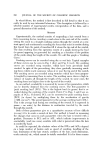
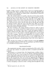
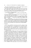
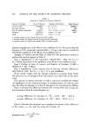
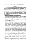
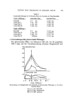
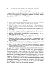
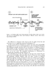
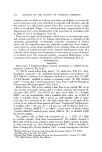
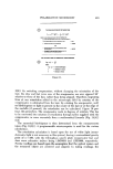
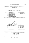
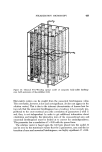
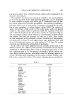
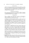
POLARIZATION MICROSCOPY 423 THE CALCULATION OF RETARDATION WHERE. IN AN EHRINGHAUS OUARTZ ROTARY COMPENSATOR: I' X is THE • DIFFERE•E IN !• • AT THE WAVELEiTH •, • IS THE WAVELEiTH IN 1• • •R WHITE LIGHT - •0 • - REF•IVE INDEX DF THE ORDIN•Y - 1.• ß - REF•IVE INDEX M THE E•R•RDINARY WAVE IN •E P•TE ß x - 1.Wl• i - •E •LE M I•LINAT• OF •E •E OF THE • RE•T• TD • ZE•O •TI• THE CALCULATION OF NUMERICAL BIREFRINGENCE Figure 11. 8(B)). By switching compensators, without changing the orientation of the hair, the slow and fast wave axes of the compensator are now opposed 90 ø relative to those of the hair, rather than being aligned. Therefore, beginning from •b, any retardation added to the microscopic field by rotation of the compensator, is subtracted from the hair. By rotating the compensator, until no birefringence or light is present in the center of the hair or at the edge of the medulla (if present), the retardation can be calculated. Figure 10 por- trays this procedure. The compensator reads in degrees of rotation. This has to be converted into microns of retardation through tables supplied with the compensator, or more accurately from a mathematical formula (Fig. 11(A)) (13). The numerical birefrigence is then determined from the measurements taken (Fig. 11(B)). A programmable microcomputer is used for the various calculations. The retardation calculation is based upon the use of white light (mono- chromatic light is not necessary in this system), having a conventional gravity point of k--550, with the Ehringhaus quartz plate compensator fast and slow wave refractive indices being 1.5459954 and 1.5551609, respectively. Precise readings are baseel upon the assumption that the optical system and the measured obiect are centered and aligned. In taking readings, the
Purchased for the exclusive use of nofirst nolast (unknown)
From: SCC Media Library & Resource Center (library.scconline.org)