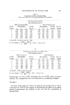
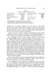
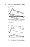
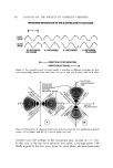
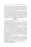
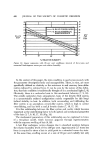
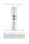
4g0 JOURNAL OF THE SOCIETY OF COSMETIC CHEMISTS index path having plane outside surfaces is formed. This arrangement vir- tually eliminates any distortion, due to the convex surfaces of the capillary tube. Another version of this device has been utilized in previous studies (12). Stress-Strain Tester In this study, stress-strain measurements are used as a reference to which the numerical birefringence is compared and correlated. A single hair fiber, 1.9 cm long, is suspended between a set of clamps. Force, applied to one end by a constant speed motor, elongates the fiber at a rate of 1.5 per cent/sec, vhile being monitored on the other end by a strain gauge transducer.* Stress versus strain graphs are plotted on XY Recorder.t Procedures 1. Microscope Alignment With the microscopic system having achieved a condition of Kohler illumination, the polarizer and analyzer are inserted and rotated to the correct position. This is best done by first rotating the bottom polarizer to a position of either qb, 90, 180, or 270 ø, and then, while focusing on an illuminated microslide, by rotating the top analyzer until maximum ex- tinction (minimal light transmission) has been reached. If the fixed first-order red compensator plate is now inserted into the compensator slot, a deep red background will appear in the microscope field. This is indicative of a N-S, E-W, polarizer-analyzer alignment, with a diagonal slow-fast wave alignment of the anisotropic compensator (2, 5). 2. Measurement o[ Numerical Bire[ringence in Human Hair Shafts: To re- call, retardation equals numerical birefringence xthickness (A =(n2-n•)d). In trying to determine the numerical birefringence, this can be rearranged to read: numerical birefringence equals retardation/thickness ((n2- n•) --A/d) (See Fig. 11(B) later on) (2). A hair shaft of approximately 4 cm length is inserted into the glass capillary tube, into which the medium weight immersion oil is dra vn from a reservoir. The capillary can then be plugged and stored in a microhemocrit tube sealer- holder. *Stathan Instruments, Inc., Oxnard, California 93030. •'He•vlett Packard, Inc., Palo Alto, California 94303.

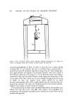
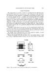
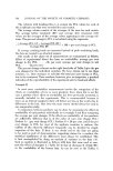
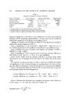
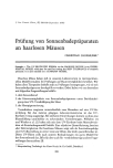
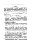
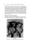
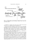
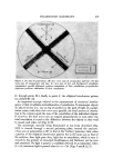
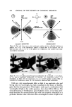
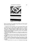
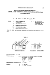
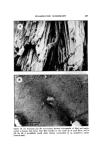
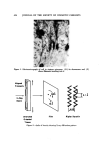
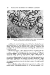
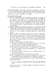
POLABIZATION MICBOSCOPY 421 Figure 9. (A) Scanning electron inicrograph shoxving elliptical axes of human hair (B) hair inside rotary device for n•easurement on its narrow axis and (C) on its wide axis. Black line is edge of capillary tube (arrow) To begin the actual measurement, with the rotary device in place on the microscope stage, a few drops of the heavy weight immersion oil is inserted into •he slot, together with the loaded capillary tube, and a coverslip is placed on top. This basic procedure is repeated each time a 'hair is viewed, as miniature air bubbles, churned by capillary rotation, become trapped under the coverslip, disrupting the homogeneous refractive index, introducing distortion and loss of resolution. The rotary microscope stage is positioned so that the hair is aligned with its longitudinal axis parallel to the slo•v wave axis etched on the first order red compensator. In this position, the sloxv wave axis of the hair is in the same axis as that of the compensator, giving the hair added retardation providing enhanced view- ing abfiity. Hair is essentially elliptical in shape, with a wide and narrow axis (Fig. 9(A)). The narrow axis is equivalent to the •hickness when the hair is resting on its wide axis, the position used for evaluating the numerical birefringence of the fiber. The hair is placed exactly on its naxxow axis. At that point, both hair edges
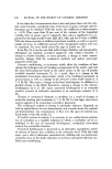
Purchased for the exclusive use of nofirst nolast (unknown)
From: SCC Media Library & Resource Center (library.scconline.org)