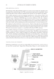
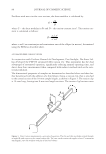
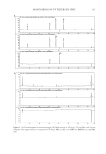
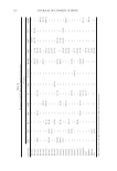
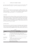
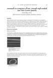
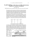
JOURNAL OF COSMETIC SCIENCE 86 For fi bers with non-circular cross sections, the shear modulus is calculated by: CL G D where G = the shear modulus in Pa and D = the torsion constant in m4. The torsion con- stant is calculated as follows: S 3 2 a b3 D a b2 where a and b are semi-major and semi-minor axes of the ellipse (in meters), determined using the FDAS as described above. AUTOMATED FIBER TORSION TESTER In conjunction with Unilever Research & Development, Port Sunlight, Dia-Stron Ltd. has developed the FTT950 automated fi ber torsion test. This instrument has the dual advantages of automated operation, signifi cantly reducing manual operating time, and direct shear force measurement when compared with indirect methods such as the rota- tional pendulum. The dimensional properties of samples are determined as described above and then fur- ther determined with the addition of a third plastic fi xing, a torsion clip, that is attached to the central section of the 30-mm sample length, as shown in Figure 3. The torsion clip is 14-mm long, leaving two 8-mm test length sections. The torsion clip has two vanes Figure 3. Direct torsion measurement—principle of operation. The two end tabs are shown rotated through an angle Θ with respect to the central torsion tab. The vane on the torsion tab applies a force F at moment arm length L onto the stainless steel pin of the force balance.

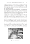
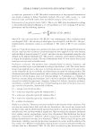
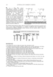
NEW METHOD FOR MEASUREMENT OF FIBER TORSION 87 (or paddles) that extend normally to the fi ber. The vanes are of equal length and mass and are consequently balanced about the axis of the fi ber. The vanes extend 7 mm on either side from the fi ber axis. A mounting block is used to accurately position the torsion clip, which is attached by press-closing two halves of a specially designed plastic tab. After preparation, the samples are loaded into a linear sample cassette (20 samples per cassette) that is mounted onto the FTT950. Figure 4 shows the main functional components of the FTT950. The key components are: a sample mounting arm with a linear micrometer drive to impart a longitudinal tensile load to the fi ber a sample mounting arm with a strain-gauge load cell to measure the load imparted independent rotational drives and high-resolution angular encoders within each mounting arm an optical encoder for determining orientation of the torsion clip and a high-resolution force balance for directly recording applied torques. As with the FDAS765, a Dia-Stron ALS1500 automated loading system is used to se- quentially transfer the samples into the FTT950 and then back to the cassette. The sam- ple is loaded into the two sample arms and is held in position by vacuum. Each sample mounting arm is independently rotated by a DC motor/gearbox combination. In addi- tion, each sample arm is fi tted with a high-resolution angular encoder that measures the rotation angle of the arm to an accuracy of 0.075°. After loading the sample, the fi ber is in a relaxed state, with the weight of the torsion clip pulling the fi ber down. The motorized sample arm is then driven out until a known lon- gitudinal force is applied to the fi ber. The target extension force and rate are determined by the user within the UvWin software. When the target force is achieved, the motorized drive is automatically stopped. Figure 3 shows a diagram of the test set-up, and Figure 4 is an annotated photo of the experimental assembly. The orientation of the torsion clip is determined by rotating both sample arms simultaneously away from the force balance (clockwise as viewed in Figure 4). As the sample rotates, the right-hand vane on the torsion clip passes through an opti- cal encoder. The rotation is then halted. When the measurement run begins, the left- hand vane is rotated into contact with the force balance. Once contact is detected, the Figure 4. FTT950 measurement head.
Purchased for the exclusive use of nofirst nolast (unknown)
From: SCC Media Library & Resource Center (library.scconline.org)