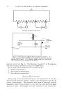
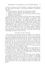
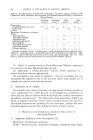
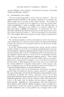
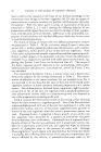
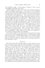
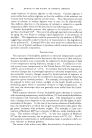
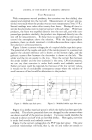
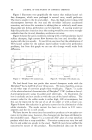
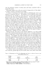
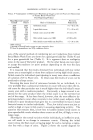
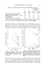
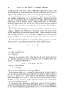
406 JO[SRNAL OF THE SOCIETY OF COSMETIC CHEMISTS TEST PROCEDURE With nonaqueous aerosol products, the container was first chilled, then opened and emptied into the test cell. Measurements of current and po- tential were made when the product was at room temperature (70 to 75øF.). Second readings were taken after twenty-four hours. During all time in- tervals the electrodes were in external contact with each other. With foam products, the foam was expelled directly into the test cell, and with com- pressed gas products similarly, the product was dispensed directly into the test cell for measurements. In these tests no special efforts were made to control the atmosphere above the solution. With the liquid propellent products, there no doubt remained a trichlorofluoromethane vapor above the solution in all measurements. Figure 1 shows a current-voltage plot of a typical shellac type hair spray. The potentials of the couple and each of the metals present in a seamed can against the calomel reference cell is shown at the bottom right, and the galvanic current flow between the electrodes is shown at the left. The solder and the tin are anodic to the iron. Since the current flow between the anode (solder) and the iron (cathode) is the same, 1.30 microamperes, we can say that corrosion is under both anodic and cathodic control. Solder corrosion could be expected, but because of the low current values, it would not be of considerable consequence except where the solution of small amounts of lead would be deleterious to the product. 600 - -• )lder • MICROAMPERES MILLIVOLTS -- Fe/Sn Sol -1 30 Couple. .410 • Sn/FeSol -0 03 Fe.. . 205 -- • 8ol/S• Fe +1 30 Sn 420 Sol 500 } 2 3 4 MICROAMPERES Figure 1.--Shellac type hair spray. MICROAMMILLIV 2 3 4 MICROAMPERES Figure 2. Modified shellac type hair spray. Figure 2 is a shellac type hair spray in which the shellac has been partially esterified. The relative potentials have not changed but the current values are about one-half of the previous product. Corrosion would therefore be reduced to about one-half with an esterified shellac. Here again, corrosion is under both anodic and cathodic control. Figure 3 is the current-voltage plot of a PVP type hair spray. The same potential relationships still hold, that is, the tin and solder are anodic to

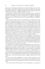
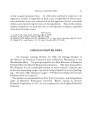
CORROSION TESTING OF AEROSOL PRODUCTS 407 the iron however, the current values are extremely low, indicating very little corrosion would take place with this particular formulation. This plot is not to be taken as indicative of all PVP hair spray formulations, since minor quantities of additives can cause a very large change in the corrosion picture. 400- MICROAMPERES MILLIVOLTS Fe/Sn-SOl TO 200 --- Sn/Fe-SOl -0 04 Fe 335 SOl/Sn Fe '150 480 1 2 3 4 Figure 3. PVP type hair spray. 300 j J MILLIVOLT/--490.385 I I Fe/SO Sol ....
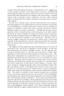
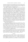
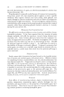
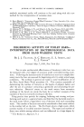
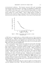
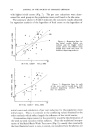
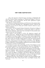
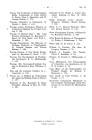
MICROAMPERES - 1 40 Couple • I I Sn/Fe-SOl .... - 0 05 Fe =• I I SOl/SO-Fe + 1 40 SO 440 / 100 I•- I Sol 535 I ] ' 1 2 3 4 MICROAMPERES Figure 4.--Copolymer type hair spray. Figure 4 is a similar plot for a vinyl acetate/vinyl pyrrolidone copolymer hair spray. The E.M.F. and current values are quite similar to the plot of the shellac type hair spray except that the tin potential is lower than the couple potential and, therefore, cathodic. Since tin has a higher hydrogen overvoltage (0.8(volts) than iron (0.40 volts), the cathodic functioning of the tin will slow down the cathode reaction because of polarization (hydro- gen film). Polarization is the production of a counter-E.M.F. by products formed or by concentration changes resulting from the passage of current. With all four of those hair spray products, shelf life of at least two years has been obtained. A continuous current flow of 0.04 microamperes in a can for one year will raise the iron content of a 12-ounce can only 1 p.p.m. To cause a can perforation through 0.010-inch plate in a year's time, a cur- rent flow of 0.2 microamperes, concentrated at an assumed pit size of 1 sq. m.m. would be required. Fe/SO SOl .... +6 60 200 SO/Fe Sol - 1 25 SOl/Sn Fe - 5 60 1 2 3 MICROAMPERES Figure 5.--Alcohol sulfate. t Couple 660 Fe 690 Sn 410 Sol 540 _._
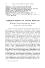
MILLIVOLTS _ 4 5 i Solder •4oo • 300 • ---- MICROAMPERES MILLIVOLTS , • 200 i Fe/SOSol +over 10 Couple 670 • i Sn/Fe SOl -4 5 Fe 705 Sol/So Fe - 5 2 So 575 ___ Sol 600 ,oo. -- I - ' I 2 3 4 5 M•CROAMPERES Figure 6.--Triethanolarnine laurylsulfate.
Purchased for the exclusive use of nofirst nolast (unknown)
From: SCC Media Library & Resource Center (library.scconline.org)