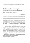
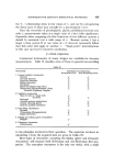
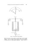
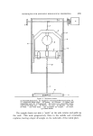
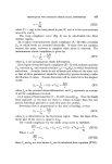
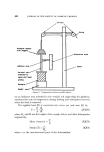
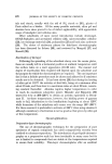
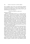
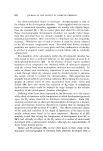
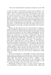
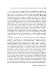
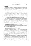
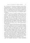
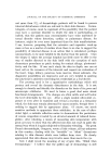
TECHNIQUES FOR ASSESSING RHEOLOGICAL PROPERTIES o 451 1%gure 4 St•ckiness meter. (a) Movable framework. (b) Gauge for measuring deflection of spring {d). (c) Adjustable knife edges. (d) Spring. (e) Grooves. (f) Upper cord connecting axle (k) to framework. (g) Lower cord connecting frame- work to test body (m). (h) Motor. (i) Gear. (j) Handle. (k) Axle. (1) Rod. (m) Test body. (n) Container for sample. (o) Scale. (p) Fixed frame. The sample draws out into a "neck" as the axle rotates and pulls up the cord. This neck progressively thins in the middle and eventually ruptures, leaving a layer of sample on the underside of the metal plate.

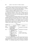
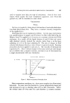
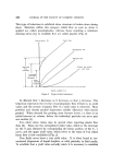
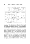
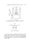
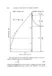
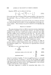
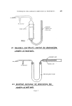
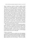
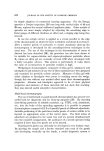
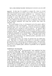
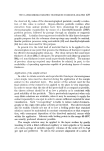
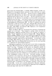
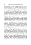
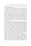
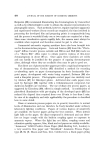
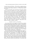
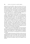
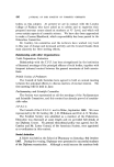
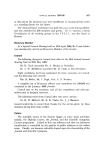
452 JOURNAL OF THE SOCIETY OF COSMETIC CHEMISTS Only "single point" determinations can be •nade with the apparatus in this form. To study non-Newtonian flow behaviour the constant speed motor is replaced by a balance pan on which different weights can be placed. The time (t) taken for rupture over a wide range of pan loadings (mg) is determined. A plot of mg against 1/t gives a curve characteristic of non-Newtonian flow (Fig. 2). Under these conditions the viscosity equations for the linear portions of pseudoplastic (%), and plastic flow (•p,), curves are (T + c)' mg 4.6 t % = r:R4 (X) and (T + c)2 (1rig - i) 4.6 t qp, = r:R 4 (XI) where T is the sample thickness, c is a constant with a value which is determined by trial and error, R is the radius of the metal plate, and i is the intercept on the 1rig axis in the mg - 1/t plot. The consistency of semi-solid materials may be examined also by shear- ing a thin layer between two parallel vertical plates (17), one of which is stationary while movement of the other is activated by a loading device. PARALLEL PLATE VISCOELASTOMETER (18) A rectangular block is cut with the sampling device shown in Fig. 5a. It is fitted with a plunger for easy removal of the sample, which is then cut into two equal halves. The pieces S• and S2 are placed on either side of a thin ribbed metal plate D (Fig. 5b) and then introduced between two ribbed plates A and B. Plate A is stationary, but B can be brought into contact with the upper surface of S• by carefully tightening with the screw device. One end of D is connected to a balance pan W by a cord which passes over two low-friction pulleys P and P,. When W is loaded S, and S• are subjected to shear, the magnitude depending on the weight used. The surfaces of S, and S• in contact with A and B remain stationary, while the maximum shear is experienced by the surfaces in contact with the two sides of D. Shear in this latter region depends on the rate at which D moves this is followed by a travelling microscope focussed on the knife edge K. To ensure minimal breakdown of sample structure, the maximum movement of D should not exceed a few mm. If temperature control is desired the apparatus can be mounted in a box made of polystyrene foam 1{--2 • thick, which contains a heating or cooling unit.
Purchased for the exclusive use of nofirst nolast (unknown)
From: SCC Media Library & Resource Center (library.scconline.org)