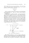
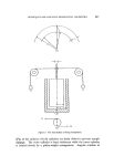
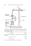
TECHNIQUES FOR ASSESSING RHEOLOGICAL PROPERTIES 445 only the instantaneous •1 prior to structure alteration. When interpreting data obtained with a capillary viscometer, corrections must be made for the following phenomena. (a) When the test sample passes from the wider tube, in which it is held initially, into the very much narrower diameter capillary, the sample is deformed around the shoulders of the wider tube. The correction which must be applied for this "end effect" (or more correctly, the "entrance effect") is minimized when the capillary has suitable dimensions, e.g. a length/radius ratio of 200/1. The effect is then insignificant compared with the pressure drop due to flow in the capillary. (b) Entry of a disperse system into the narrow capillary can lead to axial migration of the dispersed phase. This results in concentration fluctuations across the capillary, the principal reduction in concentration occurring in the sample layers adjacent to the capillary wall. (c) Not all the applied pressure is used to shear the sample. Some is used to impart kinetic energy to the sample when it enters the capillary. This effect is more significant than (a). (d) The stress S O required to produce flow at any point in a capillary at a distance R from the axis is given by S O = PR/2L (I) where P is the applied pressure, and L is the capillary length. Near the axis R is very small so that P would have to be infinitely large for PR/2L to exceed S O . This is not possible under experimental conditions. There- fore, there is always a thin layer of sample near the axis which moves through the capillary as a solid plug ("plug flow"). Detailed discussion of corrections to be made for the above, and other, phenomena is found elsewhere (13). When deriving the equation for flow in a coaxial cylinder viscometer, only the forces exerted by the sample on the curved surfaces of the cylinders are considered. However, if the inner cylinder is wholly immersed, forces are also exerted on both its ends. If the upper end of the inner cylinder is left uncovered the effect due to the lower end can be estimated by immersing the inner cylinder to different levels in the sample and measuring the ratio torque/angular velocity. When this ratio is plotted against the depth of immersion (i) a linear relationship should be obtained which gives a negative intercept on the i axis. This represents the correction to be added to i. Newtonian viscosity data obtained with a failing sphere viscometer

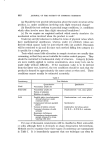
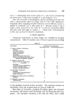
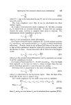
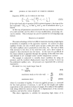
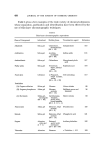
446 JOURNAL OF THE SOCIETY OF COSMETIC CHEMISTS are interpreted by Stokes's law for a sphere descending through a liquid at constant speed. If the sphere is large in comparison with the diameter of the tube through which it falls a more complex equation has to be used. Recently, Scott-Blair and Oosthuizen (4) have shown that several tests can be made on a single sample provided very small spheres are used. By rotating the tube carefully between tests unsheared material becomes available for further tests. Systems deviating only slightly from Newton- ian behaviour can also be examined by using spheres of different radii and densities (5). The ultrasonic viscometer operates on principles which are different from those of other viscometers. A probe and an electronic computer are the essential components. At the end of the probe is a thin alloy steel blade which is excited by a short electrical impulse, so producing ultrasonic shear waves in the medium around the probe. The energy involved in shearing the sample is translated into viscosity units by the computer. Whilst this instrument lends itself to automatic control of h, and detection of deviations therefrom, its application is limited to Newton- ian fluids since only one rate of shear is available. Table III summarizes the equations required for calculating v, S, h, and yield value, from data acquired with the principal types of viscometers discussed in this section. Corrections for "end effect," kinetic energy, etc., should be introduced where necessary. In capillary viscometers both S and v vary from 0 at the centre of the capillary to a maximum at the wall. When considering non-Newtonian flow it is customary to base the calculation on conditions prevailing at the capillary wall. Co-axial and cone-plate viscometers are particularly useful for studying the consistency of semi-solids since they offer a wide range of v extending down into a region of very low shear. The latter, i.e. 1 sec% is suitable for studying stationary structure. For many practical purposes the Haake "Rotovisko" is the most versatile instrument as it comprises both coaxial and cone-plate viscometers. The Weissenberg rheogoniometer offers facilities for both rotational and oscillatory shear. Oscillatory shear is particularly useful for studying structure since small amplitudes affect structure to a lesser extent than complete rotation. Study of "stationary" structure Rheological studies are not restricted to measuring •. Other para- meters can be derived for a disperse system by studying the creep behaviour in a low shear coaxial cylinder viscometer. In one form of the instrument
Purchased for the exclusive use of nofirst nolast (unknown)
From: SCC Media Library & Resource Center (library.scconline.org)