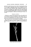
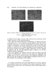
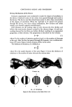
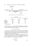
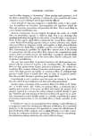
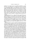
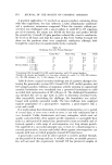
SCANNING ELECTRON MICROSCOPIC TECHNIQUES 611 the instrument, reveals extreme architectural detail. Sample preparation is relatively simple. If the sample is conductive it need only to be fastened to the sample mount. Our experience has sho•vn that micrographs of hair up to 1000x may be obtained by this simple mounting procedure. For greater defi- nition of features and magnifications to over 10,000x, the hair is coated with a thin layer of metal, usually a gold palladium alloy. The SEM is fundamentally different from its TEM counterpart in that the electrons used to produce the image normally are not those from the electron source but lo•v-cncrgy (secondary) electrons released from the surface of the sample. Although the signal is typically produced by these secondary elec- trons, an image can be produced by any signal resulting from the interaction of the high electron source with the sample. Such interaction produces X-rays, uv radiation, deflected (backscattered) electrons, ir radiation, etc., all of •vhich •vith the proper detection system could produce an appropriate signal. The high-energy beam, usually originating from a heated tungsten source, is accelerated, alemagnified, and focused to produce a beam spot of approxi- mately 50 A. Deflection coils placed between the last lens provide means for X-¾ scanning of the specimen in a rectangular raster. When the electron source strikes the specimen, lo•v-cncrgy electrons are released from the sur- face. These secondary electrons are dra•vn to a collector and phototube. The instrument electronics are such as to produce a synchronism between the electron beam and a spot on a cathode ray tube, resulting in a one-to-one correspondence between the position of the electron beam on the specimen and that of the spot on the cathode ray tube. The result is an image produced on a television screen allowing the viewer to infer a three-dimensional struc- ture from a two-dimensional screen. The SEM was chosen for this study because the micrographs produced contain much more topographical information than other microscopic tech- niques. The images produced reveal the true surface structure over a •vide range of magnifications. It is obvious that for even relatively lo•v magnifica- tions, the SEM has distinct advantages over a standard optical microscope for example, only the SEM could reveal cuticle uplift or fiber flyaway as shown on Figs. 1, 2, and $. Historgt Electron microscopy has greatly extended our insights into the structure of hair. The first application of the instrument to this field •vas initiated by Zahn in Germany in the early 1940's (1). This •vork was continued by others in the United States, Netherlands, and Australia, and by 1948 various methods of replicating the surface of hair •vcrc devised (2). Ho•vcvcr, because of instru- ment limitations and the nonconductivcncss of hair, little work was performed directly on hair itself. Most of the •vork involved the use of a metallic con- ductive coating.

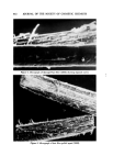
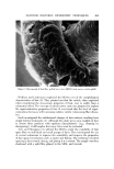
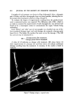
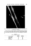
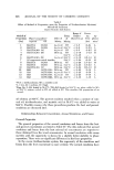
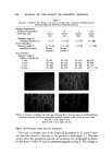
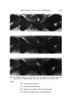
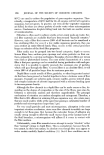
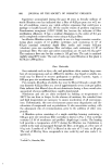
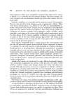
619. JOURNAL OF THE SOCIETY OF COSMETIC CHEMISTS Figure 1. Micrograph o[ damaged hair fiber (250X) showing exposed cortex , ."'."'•' .. ...:: : .,,'.:%.. '..'•.'. •.'•.•,, ..: :'":. ,-i- •. •.:":::. '.:. ...•.. .......... .-.-c',,....' .?--:...•..•-•:•....::¾:•- •,•••'" '• . '-- • :-•,•' ..., .• ...... .: ':, .... .• .... •.. "". :: .... . .... ...,...•. ..... .... ,••...••..•......•..•,..,•,• .,.. ø' -.. .. ß .• '* ....,,. '-"• ......... •,•.,,.,..'•'•." 'r'.:.-'•.'.. • ' .... ' ?' '"" ':'.Z•"' '*' • ...... • .." "•'•'. '- --'-•'•-'••' -:•r-½ . .:.' a... ,. % " •. % .*,,. . ',-,,,, . . .½•. . .•,f%.•.•--:c•.. -'.'-.-.•-•-,, .::..:-..-.-. ... .- • , ,•."" • .... .,.. :.?,-.,?:•:..•.-•,-•......•,.............:-. •' • ,.'" • "'•. '-i.. "....'"'"'??S?'"--,.•?."•'•:/:" '"'../'-'- ..... Figure 2. Micrograph o[ hair fiber pulled apart (300X)
Purchased for the exclusive use of nofirst nolast (unknown)
From: SCC Media Library & Resource Center (library.scconline.org)