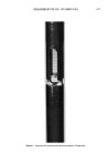
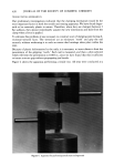
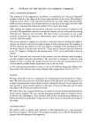
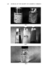
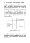
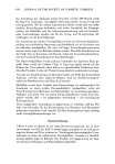
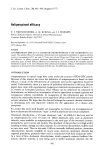
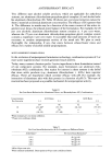
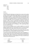
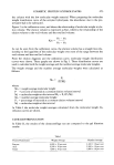
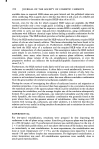
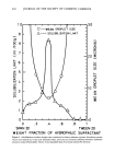
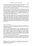
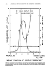
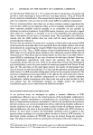
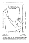
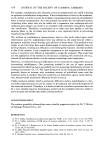
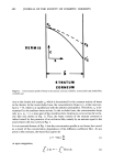
420 JOURNAL OF THE SOCIETY OF COSMETIC CHEMISTS TENSILE TESTING EXPERIMENTS Our preliminary investigations indicated that the clamping mechanism would be the most important factor in both the tensile and tearing apparatus. We have found finger- nails to be extremely plastic in nature. Therefore, when they are clamped between 2 flat surfaces, they almost immediately assume the new dimensions and slide from the clamp when a force is applied. To alleviate this problem, it was necessary to construct a set of clamping jaws having di- rectional serrated faces. The serrations act as miniature "teeth" and grip the nail securely without weakening it to such an extent that breakage takes place within the jaws. Because of plastic deformation by the nails, it is necessary to insert shims to limit the penetration of the gripping "teeth." Each nail is measured, and then a shim selected which will limit the penetration to 0.005 in., since we have found that this is sufficient to insure a secure grip without propagating jaw breaks. Figure 4 shows the apparatus performing a tensile test. All tests were conducted at a ! Figure 4. Apparatus for performing tensile tests on fingernails

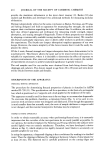
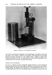
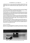
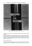
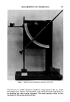
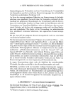
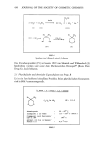
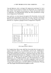
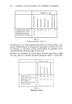
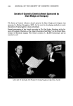
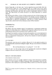
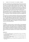
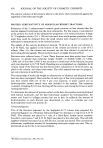
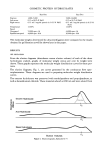
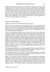
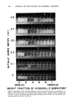
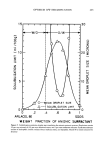
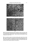
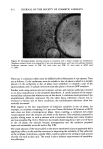
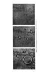
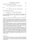
MEASUREMENTS ON FINGERNAILS 421 crosshead speed of 0.2 in./min with the machine calibrated to measure forces in the range from 0 to 20 lb. In these initial tests, a total of 196 samples were tested. The tensile strength values determined from these samples ranged from 4,464 to 17,081 lb/in. 2 TEARING TEST APPARATUS The objective of the tearing test is to simulate the action that occurs when a fingernail is torn. In order to gain a better understanding of the mechanisms involved, a "living" fingernail was torn in situ, and the results were carefully observed. As a result of the in situ tearing experiment, we concluded that the action involved closely resembled that of a piece of paper being held in both hands and torn. Once the initial break has occurred, the stresses concentrate at the point of failure and propagate the tear along the path of least resistance. In order to translate this action to a physical test, it was evident that the clamping jaws must be free to rotate so that the stresses could follow the line of the tear. This was achieved by attaching the jaws by means of a pin whose axis coincided with the edge of the nail where the tear would originate. Figure 5 shows the clamping jaws with i jaw open to reveal the clamping "teeth." During the actual test, stress is applied to the edge of the nail until failure begins to oc- cur. As the test proceeds, the jaws rotate concentrating the stress at the point where failure is occurring. Figure 6 shows the apparatus modified for tearing tests. The tests were conducted at a crosshead speed of 0.05 in./min with the machine calibrated to measure forces in the range from 0 to 20 lb. TEARING TEST EXPERIMENTS Specimens for the tearing experiments are prepared in the same way as those em- ployed for the flexural strength test. In this case, however, there were no standard Figure 5. Clamping jaws used to secure tensile and tearing specimens for testing
Purchased for the exclusive use of nofirst nolast (unknown)
From: SCC Media Library & Resource Center (library.scconline.org)