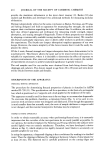
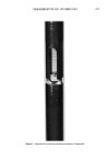
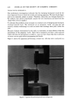
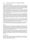
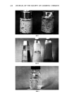
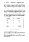
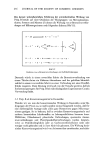
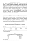
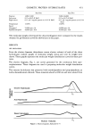
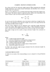
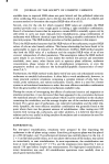
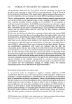
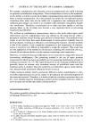
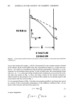
418 .% ,-v v JOURNAL OF THE SOCIETY OF COSMETIC CHEMISTS Figure 2. Apparatus for cutting fingernail test specimens covered with a rigid plastic backing plate. A movable plunger is brought in contact with the plastic, and a weight is applied to the plunger. The weight forces the sample between the blades resulting in a clean sample, which is parallel to within a few hundred thousands of an inch. All of the specimens used for these experiments were conditioned to 25øC and 65 per cent RH before testing. FLEXURAL TESTING EXPERIMENTS As soon as a sufficient quantity of fingernail samples had been cut and conditioned initial experiments aimed at determining the capabilities of the apparatus were begun. During testing, the samples were subjected to a total deflection of 0.02 in. at a crosshead speed of 0.05 in./min. The testing machine is calibrated to measure forces in

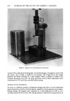
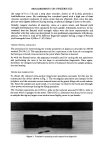
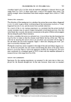
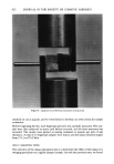
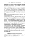
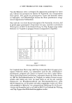
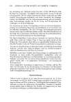
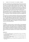
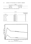
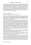
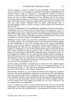
MEASUREMENTS ON FINGERNAILS 419 the range of 0 to 2 lb and a strip chart recorder, driven at 10 in./min, provides a load/deflection curve. By combining low crosshead speed with a high rate of chart traverse, excellent resolution of stress-strain data are obtained. Also, since the sam- ples are only slightly deflected during testing, no physical damage is done to the nails. Initially, tangent modulus of elasticity, stress at a given strain, and flexural yield strength determinations were calculated for each sample. Ultimately, however, we de- termined that the flexural yield strength values were the most representative and thereafter only that value was determined. In our preliminary experiments with this ap- paratus, we tested a total of 92 different fingernail samples having a range of flexural yield strengths from 4,928 to 17,653 lb/in. 2 TENSILE TESTING APPARATUS The procedure for determining the tensile properties of plastics is described in ASTM method D-638 (12). The specifications call for a specimen in the form of a rectangular bar having a reduced cross-section at the point where fracture is desired. As with the flexural tester, the apparatus normally used for cutting the test specimens and performing the tests is far too large to accommodate fingernails. Once again, therefore, we designed and fabricated a series of miniature fixtures for sample prepara- tion and testing. TENSILE BAR FABRICATION To obtain the reduced cross-section (dog bone) specimens necessary for this test we constructed the device shown in Fig. 3. The rectangular specimens are clamped in the template, and the necessary excess material removed by gently filing with a tool makers file. Since the samples are quite small, it is necessary to observe the work area through a low power microscope during the filing operation. The resultant specimens are 0.032 in. wide in the reduced area and 0.100 in. wide in the area which is gripped in the tester. The 0.032 in. dimension was found to be crucial as samples having any larger cross-section were highly prone to jaw breaks. Figure 3. Template for preparing tensile samples from fingernails
Purchased for the exclusive use of nofirst nolast (unknown)
From: SCC Media Library & Resource Center (library.scconline.org)