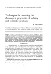
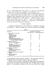
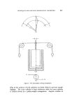
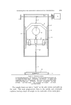
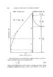
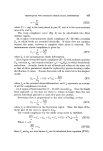
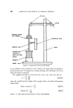
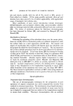
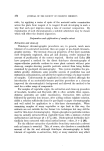
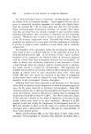
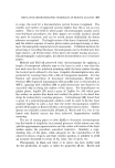
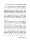
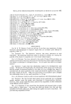
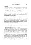
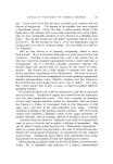
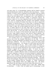
444 JOURNAL OF THE SOCIETY OF COSMETIC CHEMISTS Table III 1 ' •' RADIANS•EC, NEWTONIAI4 I I RATE OF •= • SHEAR PR • - 3G ........ '-- Gz=•TRAPOtATEO VALU[ • TO•U[ •0• cone angle, provides uniform shearing conditions throughout the whole of the sample. In a capillary viscometer v varies from 0 at the capillary axis to a maximum at the capillary wall surface. Viscosity measurements in a coaxial cylinder viscometer involve rotation of one of the cylinders. If the outer cylinder is rotated then the torque transmitted to the inner cylinder is measured. In this case v varies from a maximum at the rotating cylinder surface to a minimum at the inner cylinder surface, but by suitable design, so that the gap between the two cylinders is small, this shear gradient is minimized. When the outer cylinder remains stationary and the inner cylinder rotates, e.g. Haake "Rotovisko," • is calculated from the viscous drag exerted on the latter by the sample. Capillary viscometers cannot be used to study the effect of time of shear at any v on Yl since the sample in the capillary is continuously changing. As will be shown later, such information can be of value when elucidating the structure of concentrated dispersions. On the other hand, this deficiency can be advantageous when dealing with systems showing time-dependent structure breakdown and recovery if one is interested in

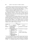
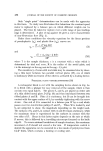
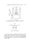
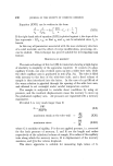
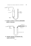
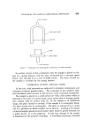
TECHNIQUES FOR ASSESSING RHEOLOGICAL PROPERTIES 445 only the instantaneous •1 prior to structure alteration. When interpreting data obtained with a capillary viscometer, corrections must be made for the following phenomena. (a) When the test sample passes from the wider tube, in which it is held initially, into the very much narrower diameter capillary, the sample is deformed around the shoulders of the wider tube. The correction which must be applied for this "end effect" (or more correctly, the "entrance effect") is minimized when the capillary has suitable dimensions, e.g. a length/radius ratio of 200/1. The effect is then insignificant compared with the pressure drop due to flow in the capillary. (b) Entry of a disperse system into the narrow capillary can lead to axial migration of the dispersed phase. This results in concentration fluctuations across the capillary, the principal reduction in concentration occurring in the sample layers adjacent to the capillary wall. (c) Not all the applied pressure is used to shear the sample. Some is used to impart kinetic energy to the sample when it enters the capillary. This effect is more significant than (a). (d) The stress S O required to produce flow at any point in a capillary at a distance R from the axis is given by S O = PR/2L (I) where P is the applied pressure, and L is the capillary length. Near the axis R is very small so that P would have to be infinitely large for PR/2L to exceed S O . This is not possible under experimental conditions. There- fore, there is always a thin layer of sample near the axis which moves through the capillary as a solid plug ("plug flow"). Detailed discussion of corrections to be made for the above, and other, phenomena is found elsewhere (13). When deriving the equation for flow in a coaxial cylinder viscometer, only the forces exerted by the sample on the curved surfaces of the cylinders are considered. However, if the inner cylinder is wholly immersed, forces are also exerted on both its ends. If the upper end of the inner cylinder is left uncovered the effect due to the lower end can be estimated by immersing the inner cylinder to different levels in the sample and measuring the ratio torque/angular velocity. When this ratio is plotted against the depth of immersion (i) a linear relationship should be obtained which gives a negative intercept on the i axis. This represents the correction to be added to i. Newtonian viscosity data obtained with a failing sphere viscometer
Purchased for the exclusive use of nofirst nolast (unknown)
From: SCC Media Library & Resource Center (library.scconline.org)