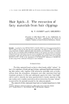
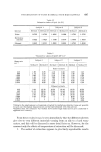
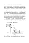
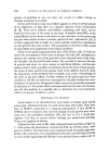
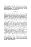
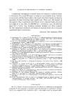
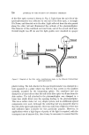
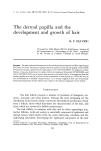
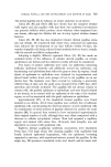
730 JOURNAL OF THE SOCIETY OF COSMETIC CHEMISTS of the fibre optic system is shown in Fig. 2. Light from the exit slit of the spectrophotometer was collected by one tail of the fibre optic, a rectangle 10 X 2 mm, and directed on to the skin. Light reflected from the skin passed along the other tail and illuminated the cathode of the photomultiplier. The diameter of the combined end was 6 mm, and of the second tail 3 mm. Overall length was 35 cm and the light guides were sheathed in opaque (• Phot lluminat!Tail L•F Tail. o Figure 2 Diagram of the fibre optics modifications made to the Hitachi Perkin-Ehner spectrophotometer. plastic tubing. The tail attached to the spectrophotometer was clamped in a tube mounted on a plate which was held by four screws in the position normally occupied by the integrating sphere. The combined end was clamped in a brass tube so that the end of the fibre optic was 3 mm from the skin surface. The tail attached to the photomultiplier was clamped in a brass boss which fitted over the opening leading to the photomultiplier. This was a rather crude, but very simple system, and no additional optical components were used. Although the collecting tail was mounted close to the exit of the spectrophotometer, there was some loss of light but there was still sufficient light available for this particular purpose. However, in applications where a high degree of purity of the light is required, with the consequent use of narrow slits, then it may be necessary to ensure that the

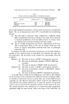
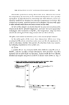
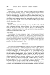
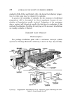
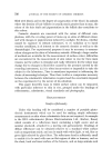
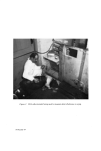
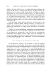
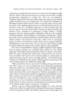
Figure $ Hitachi Perkin-Elmer spectrophotometer with light guides attached. Facing page 731
Purchased for the exclusive use of nofirst nolast (unknown)
From: SCC Media Library & Resource Center (library.scconline.org)