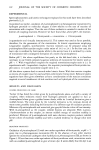
182 JOURNAL OF THE SOCIETY OF COSMETIC CHEMISTS EXPERIMENTAL INSTRUMENTATION A schematic for the apparatus is shown in Figure 1. The apparatus consists of a source (S) of dry air (dew point less than -40øC). Conventional pressure regulation and flow control through the use of valving were used. Humidification was accomplished by blending a stream of dry air with a stream of moist air. The moist air was achieved by passing dry air through an R.J. Harvey permeation cell, C-1, (R.J. Harvey Instrument Corp., 77 Brookside Place, Box 98, Hillsdale, NJ 07642). The cell is equipped with a source of distilled water and a polymeric membrane which regulates the diffusion of water into the air stream. Temperature control of the humidification process is accomplished with a conventional hot air laboratory oven (O-!) modified to accept the R.J. Harvey permeation cell. R Figure 1. Schematic of the in vitro apparatus. Where S-dry air R-regulator V• •o-valves 0•_2-oven C•.2-cells T•.•-thermistors TH-thermometer H•.2-dew point hygrometers B-bubblemeter RC-recorder TI-timer The humidity is monitored with an EG&G Model 880 dew point hygrometer, H-! (Environmental Equipment Div., 151 Bear Hill Road, Waltham, MA. 02154). The sample of polymeric film is placed into a second R.J. Harvey permeation cell (C-2) which is temperature controlled by a second hot air laboratory oven (0-2) and is monitored by a second dew point hygrometer (H-2). Temperatures are recorded using a Yellow Springs Instrument Model 8720-23 Thermistor Thermometer, TH with appropriate thermistors. The hygrometer signals are recorded on an appropriate strip chart recorder (RC). METHOD The polymeric film (Nylon 6 film, Capran, manufactured by Allied Chemical Corp. Morristown, NJ 07960) is placed into the sample cell, C-2, so that one side is in contact

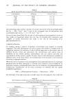
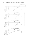
TRANSEPIDERMAL MOISTURE LOSS 183 with deionized water and the other side is in contact with the air stream. The film is allowed to come to equilibrium with a 0% RH. The dew point of the air stream is monitored and the trans film moisture loss rate (TFML) is determined by calculating the rate at which water appears in the air stream as mg of water/cm2/hr. If desired, the relative humidity of the gas stream can be varied and the TFML determined for any % RH. The base rate for the film is designated as TFML-B. The product to be evaluated is loaded onto the surface area of the polymeric film on the side exposed to the air stream. A weight (W) in grams is coated onto the cell area (A) to give a product thickness (on a whole product basis) of 0.025 mm according to equation (1). 0.025 mm -- W x 10 (1) Where W = Weight in grams 10 = 10 mm/cm A = Area in cm 2 G = Specific gravity in g/cm 3 AxG The sample is then allowed to come to equilibrium with the specified air stream and the trans film moisture loss rate (TFML-S) of the sample is determined. 2.5 2.0 1.5 1.0 0.5 0 10 20 30 40 50 60 70 80 90 100 % RELATIVE HUMIDITY Figure 2. The Trans Film Moisture Loss rate (TFML) for three samples of the experimental polymeric substrate. Beginning (&), middle (©), and end (I) of roll.
Purchased for the exclusive use of nofirst nolast (unknown)
From: SCC Media Library & Resource Center (library.scconline.org)