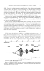
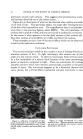
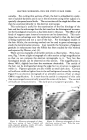
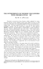
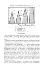
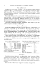
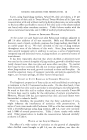
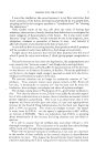
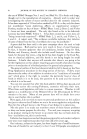
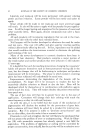
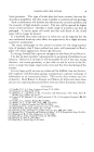
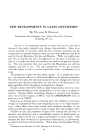
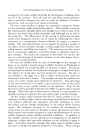
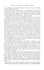
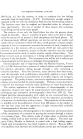
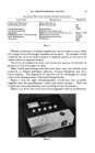
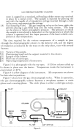
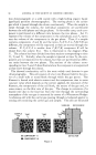
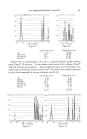
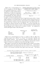
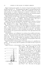
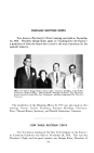
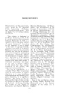
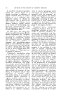
GAS CHROMATOGRAPHIC ANALYSIS GAs-LiquiD PARTITION CHROMATOGRAPHIC INSTRUMENTS 95 Instrument Manufacturer Model No. Fisher-Gulf Partitioner Fisher Scientific Co. Kromo-Tog, Fraction Burrell Corporation Vapor Fractometer Perkin-Elmer Gas Chromatograph Beckman Instruments, Inc. Aerograph Wilkins Instruments & Research, Inc. Hallikainen-Shell Chromatograph Hallikainen Instruments Reco Distillograph Research Equipment Corp. Aromacon Podbielniak A-1 B-1 154B Mod•i •100 llllA D-2000 9400 9475 Figure 1. Marked retardation of sample components can be made to occur when the strong forces of hydrogen bonding can be used. An example of this would be the use of an alcohol column to separate amines, or the use of an amine column to separate alcohols. The forces of complex formation and interaction because of similarity of I groups can also be brought into play. Many liquid partitioning materials have been used and include such •materials as dibutyl phthalate, silicones, tricresyl phosphate and dim- I butyl maleate. The ingenuity of chemists will be challenged for many years in the testing and use of new partitioning liquids. Figure 1 lists the eight chromatographic instruments now available •together with the manufacturers' names and model numbers. There are at least two more manufacturers now working on such instruments. Figure 2 is a front view of the Gas Chromatograph made bv the Beckman Figure 2.

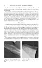
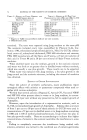
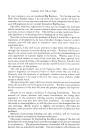
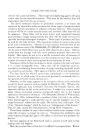
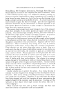
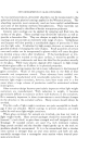
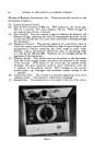
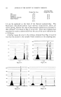
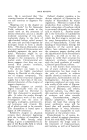
96 JOURNAL OF THE SOCIETY OF COSMETIC CHEMISTS Division of Beckman Instruments, Inc. There are five dial controls on the instrument as follows: (1) Coarse Current Control. (2) Fine Current Control, 0-400 ma. With helium as the carrier gas, 250 ma. is normal. For trace analysis, 350 ma. With nitrogen or air as carrier gas, 150 ma. is normal. (3) Zero Control. The zero control is used to balance the detector cell filament bridge, adjusting the Gas Chromatograph electrical circuit so that the recorder pen is at zero when carrier gas is flowing through the instrument. (4) Sensitivity Control. This permits selection of a sensitivity value at which the output trace will be sufficiently high for good analysis and interpretation without exceeding the chart range at peak value. Position 1 gives the greatest sensitivity, then in decreasing order 2, 5, 10, 20, 50, 100 and 200. Positions can be changed during the operation of the instrument. (5) Polarity Switch. This switch turns on the power to the instrument I from the 6-volt storage battery and selects the polarity of the output of the recorder. With helium as the carrier gas, all samples except I hydrogen will give relatively positive chart indications with the: -I- position of the polarity switch. With nitrogen as the carrier, several gases, e.g., hydrogen and methane, require setting in the• - position. (6) Carrier Gas Flow. This control is a pressure regulating valve and a• capillary orifice. The pressure is indicated on the gauge. (7) Sample Inlet. The sample inlet on the right of the top of the instru-. Figure 3.
Purchased for the exclusive use of nofirst nolast (unknown)
From: SCC Media Library & Resource Center (library.scconline.org)