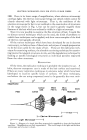
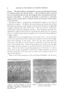
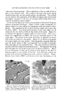
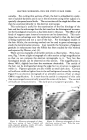
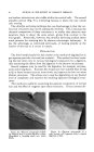
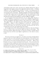
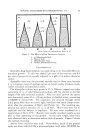
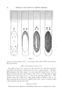
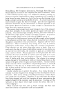
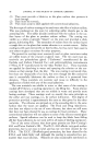
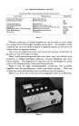
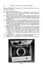
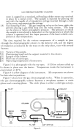
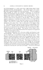
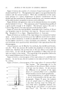
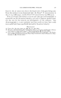
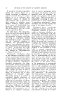
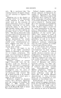
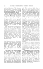
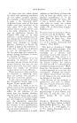
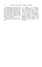
GAS CHROMATOGRAPHIC ANALYSIS 97 ment is capped by a standard, self-sealing rubber serum cap retained in place by a metal cover. The sample is injected by piercing the cap with the needle of a hypodermic syringe inserted through a hole in the cover, and emptying the syringe. (8) Gas Sampling Valve. The gas sampling valve on the lower right side permits placing a gas filled loop into the valve system. This loop can be above or below atmospheric pressure. The pressure at which the sample is introduced is dependent on the temperature at which the column is operated and the vapor pressure of the least volatile com- ponent at that temperature. The time required for the various components of a sample to pass through the chromatographic column to the detector cell, and the degree of resolution as indicated by the trace on the strip chart, vary with several factors: (1) Nature of the sample. (2) Partitioning liquid and the support material in the column. (3) Length of the column. (4) Flow rate of carrier gas. (5) Opera ting temperature of instrument. Figure 3 is a photograph with the top open. A 12-foot column coiled up is shown in place over the heater. Temperature inside the instrument is maintained at 40øC. Figure 4 is a flow diagram of the instrument. All components are shown in their relative positions. Figure 5 shows how the gas chromatograph works. When in operation, the gas chromatographic column becomes a two-phase system--a static I phase and a moving phase. The static phase is either a solid (gas adsorp- INLET VACUUM COLUMN PRESS PRESS REG GAGE • R•'F •CE VALVE FILTER CAP ORIFICE Figure 4.

98 JOURNAL OF THE SOCIETY OF COSMETIC CHEMISTS tion chromatograph) or a solid coated with a high boiling organic liquid (gas-liquid partition chromatography). The moving phase is the carrier gas which is passed through the column continuously. When the sample is swept through the column, the individual components are partitioned between the solid phases and the gas phase. In favorable cases, each com- ponent is partitioned at a different ratio between the two phases. Let Fs represent the volume of the components in the solid phase, and Fg repre- sent the volume of the components in the gas phase. Then, if a sample contains components • and B, and the ratios Vg•/Vs• to V•B/VsB are different, the components will be separated as they are moved through the column. If Fv/I/Fs/I is smaller than FvB/F•B, component B will be eluted from the column first. This is illustrated in the diagram (Fig. 5). The column has been divided into three sections corresponding to time T0, T• and T2. Initially, when the sample is injected at time To, the com- ponents are not separated in the column, but they are partitioned at differ- ent ratios between the two phases. The sections of the column corre-', sponding to time T• and T2 then illustrate how the components are separated l as they move through the column. The thermal conductivity cell is the most widely used detector in gas chromatography. This cell consists of a hot wire filament held in the cen- ter of a small tube or metal block through which the gas passes. The filament is heated with electric current and the temperature rises to some constant value which depends on the current applied, the resistance of the filament, the temperature of the cell block, the nature of the gas and, to some extent, on the flow rate of the gas. The change in resistance of a heated wire due to the heat lost from the wire through the surroundingl atmosphere of the test gas is measured by means of a Wheatstone Bridge. A reference cell with the carrier gas passing through is balanced against a l sensing cell containing the carrier gas and sample. The cells are balanced l SAMPLE TIME TEE ß COMPONENT ß COMPONENT SENSING REFERENCE i!:•:': ::::..•: :..•:: s •:::: :•::.::: :•,":::: :•: :::::::::::s DETECTOR Figure 5.
Purchased for the exclusive use of nofirst nolast (unknown)
From: SCC Media Library & Resource Center (library.scconline.org)