SCALE-UP CONSIDERATIONS IN COSMETIC MANUFACTURE 269 equipment. High speed direct drive mixers should be avoided if fluid shear is detrimental. The use of the slow speed gear drive propeller mixers and the still slower speed tu•'bine type mixers is required if fluid shear rates must be kept to a minimum. In crystallization processes, the over-all circulating capacity must be carefully related to fluid shear to provide the proper particle size. L•QUID-LIQu•D CONTACTING There are two types of liquid-liquid contacting applications. One is the case of extraction, in which it is desired to mix two liquid phases ini- tially to effect the extraction of one component from one phase to the other, but not to produce a permanent emulsion that will not settle. The mixer produces a certain mass transfer rate which is given by the equation Rate c• K,,a (c•-c2) This indicates that the mixer provides a certain interfacial area which is the "a" term above (square feet per cubic foot of volume) and K•, film coefficient, (lb. tools. per hour per foot squared) which is related to the thickness of the stagnant film surround the droplets. The driving force causing mass transfer to take place is the difference in concentration c, of the component in phases 1 and 2. The approach of an extraction to equilibrium is defined as stage efficiency. Scale-up in these systems can be determined by knowledge of the effect of mixer and tank variables on extraction coefficient K•a, and the knowl- edge of residence time and concentration driving force on the stage effi- ciency produced. There are many different ways of carrying out liquid-liquid extraction including single batch extraction, multiple batch extraction with fresh solvent, continuous multistage extraction with fresh solvent in each stage, continuous countercurrent multistage extraction in a series of separate tanks, or continuous countercurrent multistage extraction in a mixing column. Present-day techniques allow accurate prediction of extraction processes. The other class of liquid-liquid contacting is to produce a permanent emulsion. The term permanent or stable emulsion is a relative one, since most emulsions will settle eventually. The formulation of the liquid is of major importance in these operations. If the mixer is producing a particle size which gives a greater interfacial area than the formulation will support permanently, then the emulsion will revert to its more or less stable condition. Changes in mixer design will have little effect on the ultimate product since the formulation controls. If the formulation is capable of maintaining a smaller dispersion size than

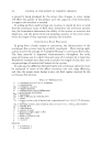
270 JOURNAL OF THE SOCIETY OF COSMETIC CHEMISTS is presently being produced by the mixer, then changes in mixer design will affect the quality of the product until the capacity of the formulation to support the emulsion is reached. In scaling up from small to large size systems, it should be born in mind that the maximum value of fluid shear determines the minimum particle size, the formulation determines the ability of the system to maintain this dispersion, and the power level and pumping capacity of the mixer deter- mines the length of time required to produce the emulsion. CoNTinUOUS FLOW PRocEssEs In going from a batch system to continuous, the characteristics of the continuous flow system must be carefully considered. Most mixing appli- cations involve the concept of "Complete Mixing" in continuous flow tanks. The feed material is dispersed instantaneously throughout the tank, some of it passes out in a short time and some of it remains for a long time. Probability methods have been used to predict the length of time that vari- ous percen tages of material will remain in the system. ]n scale-up, the difference between batch and continuous operation must be evaluated in terms of the effect of process rate and stage efficiency, and then the proper mixer design to give the fluid regime required for the continuous flow process. Kn = P = Ni, = .•. T = F = p T interl:acial area, (ft?/cu. ft. of volume) concentration centipoise, viscosity impeller diameter mathematical symbol of differential gravitational acceleration horsepower film coefficient, (lb. mols./hr./ft. =) power power number, ratio of inertia force to gravitational fi•rce, Pg/pNa/D •, dimension- less Reynolds number, ratio of inertia force to viscous force, ND=p/u, dimensionless impeller flow tank diameter volume of vessel distance at right angles to flow fluid velocity density of fluid or solid shear stress viscosity Subscripts I = Component 1 2 = Component 2
Purchased for the exclusive use of nofirst nolast (unknown)
From: SCC Media Library & Resource Center (library.scconline.org)