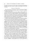
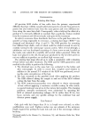
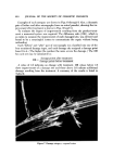
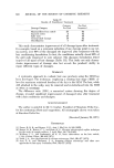
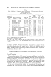
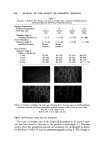
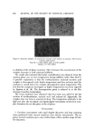
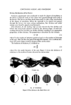
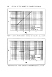
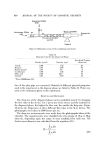
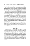
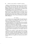
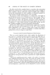
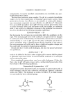
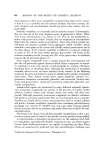
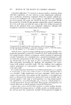
CONTINUOUS MIXING AND PROCESSING 645 0.•I9 0.146 Scllaschlik Mixer STATIC MIXER © J Unit Pipe With ß Radial Inlet ß ß ß ß J Empty Pipe .... 0.0?3 0 I0 20 50 40 50 L/d Pressure drop vs. relative length of the mixer Figure 6. Pressure drop vs. relative length of the mixer Where Ap = pressure drop in empty pipe f = Darcy's friction factor L = length of pipe D = inside diameter of pipe v = velocity of fluid go = gravitational acceleration p = density of fluid Pressure drop in the device of the same length and diameter as an empty pipe is determined by multiplying the calculated pressure drop in the empty pipe by a oeaetor, K. That is: AP•s,.• -- K AP (5) where APs•t is the pressure drop in the device. The factor, K, is a function of the geometry of the mixer elements and the Reynolds number. The values of K were determined under different conditions. To facilitate the calculation of pressure drop in the device, the values are tabulated and plotted for different conditions (Figs. 7, 8, and Table I). The factor, K, is determined according to the range of the Reynolds number,

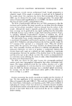
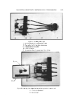
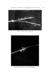
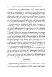
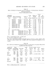
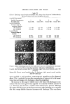
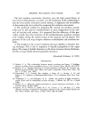
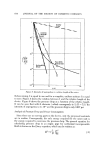
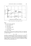
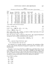
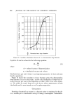
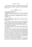
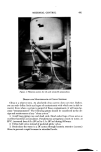
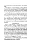
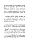
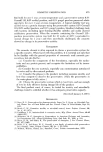
646 JOURNAL OF THE SOCIETY OF COSMETIC CHEMISTS 10 t NRe i iii i / - I I I I Illl• p• [ I I I Illll I I I I [llll • '•_•J_111ill I I I II1111 '1111 ///Illill I I III1111 l',',', [ [ , ,l[,[I i II [ Illl':[l, I]ll ] I I II1[[ ! I I I II[1 IlIl I --I-- I I II111 I I I IIIl[ I1[I I I I I I[[11 I IIIII I 111] I [ I IIIIII I I I III[]1 111I I 11111111 I I IIIt111 •- •olvo for • • 0 3 • 0 4 Figure 7. A factor rs. Reynolds number in the ]aminar ttow region (10 Nae 9, X 10 3) iiiiii iiiiii ' iiiii iiiii Ilii i I i i ii ii i i i El , ,,,,, l Ill,, I I '" ,, ,,, II!t Ill ! I I Ill I I Illl I I Ill I I Ill I III IIIIII I IIIII 11111 III1! IIII IIIIII IIIIII 11ill IIIII IIII IIIIII II1111 11111 IIIII IIII i i i i ii ] I 1 I II I I III iii!11 ........... ii... :::: iii i i iiii iiiii III IIII iii i i ii •11111 ..... III'" Ill -' HI'" lllll - 4- ........ l,ql, III '" "'" PROCEDURE: ,, II IIIIII II IIII II 1-Locate ERe IIII 111111 I III11 IIIII •sR i de fv I/ "B" at intercept 10 3 10 • I 0 • 10" NRe Figure 8. B factor rs. Reynolds number in the turbulent tto•v region (N• 9, X 10 3)
Purchased for the exclusive use of nofirst nolast (unknown)
From: SCC Media Library & Resource Center (library.scconline.org)